Support Information
3.4.2UART4 Connector
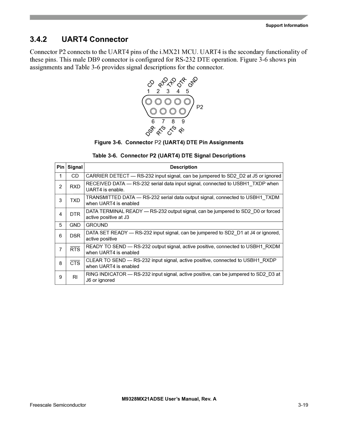
Connector P2 connects to the UART4 pins of the i.MX21 MCU. UART4 is the secondary functionality of these pins. This male DB9 connector is configured for
|
|
|
| C | D | R | X | D | T | X | D | D | T | R |
| G | N | D | |||||
|
|
|
|
|
|
|
|
| |||||||||||||||
|
|
|
|
|
|
|
|
|
|
|
|
|
|
|
| ||||||||
|
|
|
| 1 |
|
|
| 2 |
|
| 3 |
|
| 4 |
|
| 5 |
|
| ||||
|
|
|
|
|
|
|
|
|
|
|
|
|
|
|
|
|
|
|
|
|
|
| P2 |
|
|
|
|
|
|
|
|
|
|
|
|
|
|
|
|
|
|
|
|
|
| ||
|
|
|
|
|
|
|
| 6 |
|
| 7 |
| 8 |
| 9 |
|
|
|
| ||||
|
|
|
|
|
| S | R |
| T | S |
|
| T | S |
| I |
|
|
|
| |||
|
|
|
| D |
|
| R |
|
| C |
| R |
|
|
|
|
| ||||||
|
|
|
|
|
|
|
|
|
|
|
|
|
|
|
|
|
|
|
| ||||
|
|
|
| Figure | |||||||||||||||||||
|
|
|
| Table | |||||||||||||||||||
|
|
|
|
|
|
|
|
|
|
|
|
|
|
|
| ||||||||
Pin | Signal |
|
|
|
|
|
|
|
|
|
|
| Description | ||||||||||
|
|
|
|
|
|
|
| ||||||||||||||||
1 |
| CD | CARRIER DETECT — | ||||||||||||||||||||
|
|
|
|
|
|
|
|
| |||||||||||||||
2 | RXD | RECEIVED DATA — | |||||||||||||||||||||
UART4 is enable. |
|
|
|
|
|
|
|
|
|
|
|
|
|
|
|
|
|
| |||||
|
|
|
|
|
|
|
|
|
|
|
|
|
|
|
|
|
|
|
|
|
| ||
|
|
|
|
|
|
|
|
| |||||||||||||||
3 |
| TXD | TRANSMITTED DATA — | ||||||||||||||||||||
| when UART4 is enabled |
|
|
|
|
|
|
|
|
|
|
|
|
|
|
|
|
|
| ||||
|
|
|
|
|
|
|
|
|
|
|
|
|
|
|
|
|
|
|
|
|
| ||
|
|
|
|
|
|
|
|
| |||||||||||||||
4 | DTR | DATA TERMINAL READY — | |||||||||||||||||||||
active positive at J3 |
|
|
|
|
|
|
|
|
|
|
|
|
|
|
|
|
|
| |||||
|
|
|
|
|
|
|
|
|
|
|
|
|
|
|
|
|
|
|
|
|
| ||
5 | GND | GROUND |
|
|
|
|
|
|
|
|
|
|
|
|
|
|
|
|
|
| |||
|
|
|
|
|
|
|
|
| |||||||||||||||
6 | DSR | DATA SET READY — | |||||||||||||||||||||
active positive |
|
|
|
|
|
|
|
|
|
|
|
|
|
|
|
|
|
| |||||
|
|
|
|
|
|
|
|
|
|
|
|
|
|
|
|
|
|
|
|
|
| ||
|
|
|
| READY TO SEND — | |||||||||||||||||||
7 |
| RTS | |||||||||||||||||||||
| when UART4 is enabled |
|
|
|
|
|
|
|
|
|
|
|
|
|
|
|
|
|
| ||||
|
|
|
|
|
|
|
|
|
|
|
|
|
|
|
|
|
|
|
|
|
| ||
|
|
|
|
|
|
|
|
| |||||||||||||||
|
|
|
| CLEAR TO SEND — | |||||||||||||||||||
8 |
| CTS | |||||||||||||||||||||
| when UART4 is enabled |
|
|
|
|
|
|
|
|
|
|
|
|
|
|
|
|
|
| ||||
|
|
|
|
|
|
|
|
|
|
|
|
|
|
|
|
|
|
|
|
|
| ||
|
|
|
|
|
|
|
|
| |||||||||||||||
9 |
| RI | RING INDICATOR — | ||||||||||||||||||||
| J6 or ignored |
|
|
|
|
|
|
|
|
|
|
|
|
|
|
|
|
|
| ||||
|
|
|
|
|
|
|
|
|
|
|
|
|
|
|
|
|
|
|
|
|
| ||
| M9328MX21ADSE User’s Manual, Rev. A |
Freescale Semiconductor |