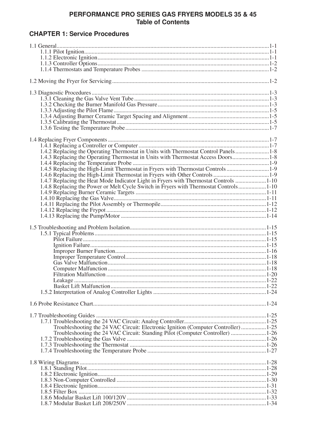
45, 35 specifications
The Frymaster 35 and 45 series fryers are well-known in the catering industry for their reliability, efficiency, and advanced cooking technologies. These models are designed to cater to medium to high-volume establishments, providing users with exceptional performance and ease of use.One of the main features of the Frymaster 35 and 45 series is their impressive fry capacity. The 35 model can handle around 35 pounds of oil, while the 45 model accommodates up to 45 pounds. This increased oil capacity means that both fryers can fry larger batches of food more efficiently, allowing for quicker service times in busy kitchens.
Another key characteristic is the high-performance heating elements. The Frymaster series utilizes V-shaped heat exchangers, which deliver rapid recovery times and consistent cooking temperatures. This technology enables the fryers to maintain optimal heat levels even during heavy usage, ensuring that food is cooked evenly and thoroughly.
The Frymaster 35 and 45 also feature built-in filtration systems. This technology helps in prolonging the life of the oil by filtering out food particles and impurities, which not only enhances the taste of the fried food but also reduces operational costs. The automatic filtration system can be programmed to run on a cycle to ensure that oil quality remains high without requiring constant manual intervention.
In terms of user-friendly design, both models are equipped with digital temperature controls, which allow chefs to precisely set and maintain frying temperatures. The intuitive control panel simplifies operation, while the integrated safety features, such as high-limit temperature controls, help prevent overheating and accidents in the kitchen.
Durability is another hallmark of the Frymaster series. Constructed from stainless steel, these fryers are built to withstand the rigors of commercial kitchens while resisting corrosion and wear. Additionally, Frymaster offers a range of accessories and options, such as baskets and lids, to enhance the functionality and versatility of these fryers.
In summary, the Frymaster 35 and 45 series fryers are top-tier options for commercial food establishments, combining substantial fry capacity, advanced heating technology, built-in oil filtration, and user-friendly controls. Their robust design and efficiency make them ideal for any kitchen looking to deliver high-quality fried foods consistently.
