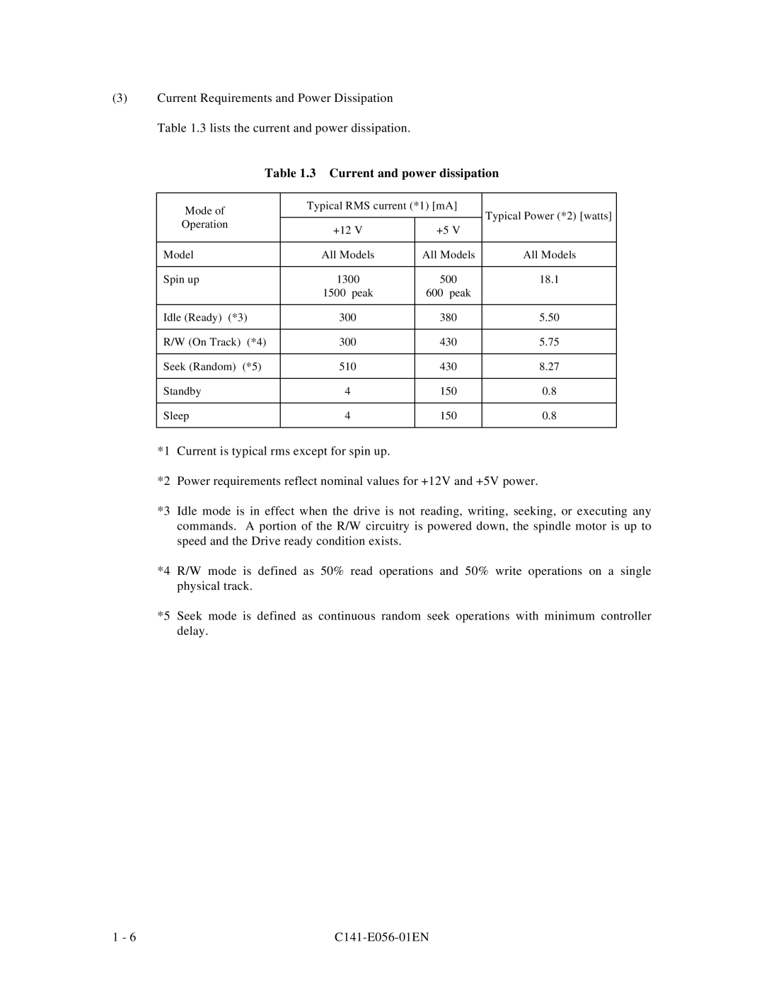
(3)Current Requirements and Power Dissipation Table 1.3 lists the current and power dissipation.
Table 1.3 Current and power dissipation | ||||
|
|
|
| |
Mode of | Typical RMS current (*1) [mA] | Typical Power (*2) [watts] | ||
|
| |||
Operation | +12 V | +5 V | ||
| ||||
|
| |||
|
|
|
| |
Model | All Models | All Models | All Models | |
|
|
|
| |
Spin up | 1300 | 500 | 18.1 | |
| 1500 peak | 600 peak |
| |
|
|
|
| |
Idle (Ready) (*3) | 300 | 380 | 5.50 | |
|
|
|
| |
R/W (On Track) (*4) | 300 | 430 | 5.75 | |
|
|
|
| |
Seek (Random) (*5) | 510 | 430 | 8.27 | |
|
|
|
| |
Standby | 4 | 150 | 0.8 | |
|
|
|
| |
Sleep | 4 | 150 | 0.8 | |
|
|
|
| |
*1 Current is typical rms except for spin up.
*2 Power requirements reflect nominal values for +12V and +5V power.
*3 Idle mode is in effect when the drive is not reading, writing, seeking, or executing any commands. A portion of the R/W circuitry is powered down, the spindle motor is up to speed and the Drive ready condition exists.
*4 R/W mode is defined as 50% read operations and 50% write operations on a single physical track.
*5 Seek mode is defined as continuous random seek operations with minimum controller delay.
1 - 6 |