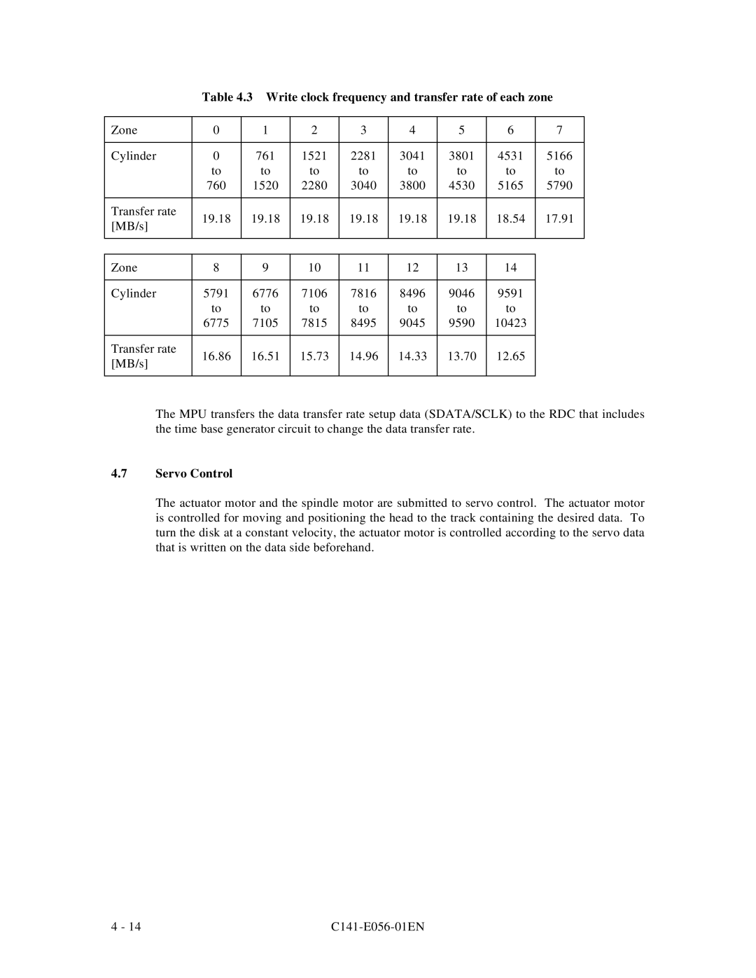
Table 4.3 Write clock frequency and transfer rate of each zone
Zone | 0 | 1 | 2 | 3 | 4 | 5 | 6 | 7 | |
|
|
|
|
|
|
|
|
| |
Cylinder | 0 | 761 | 1521 | 2281 | 3041 | 3801 | 4531 | 5166 | |
| to | to | to | to | to | to | to | to | |
| 760 | 1520 | 2280 | 3040 | 3800 | 4530 | 5165 | 5790 | |
|
|
|
|
|
|
|
|
| |
Transfer rate | 19.18 | 19.18 | 19.18 | 19.18 | 19.18 | 19.18 | 18.54 | 17.91 | |
[MB/s] | |||||||||
|
|
|
|
|
|
|
| ||
|
|
|
|
|
|
|
|
| |
|
|
|
|
|
|
|
|
| |
Zone | 8 | 9 | 10 | 11 | 12 | 13 | 14 |
| |
|
|
|
|
|
|
|
|
| |
Cylinder | 5791 | 6776 | 7106 | 7816 | 8496 | 9046 | 9591 |
| |
| to | to | to | to | to | to | to |
| |
| 6775 | 7105 | 7815 | 8495 | 9045 | 9590 | 10423 |
| |
|
|
|
|
|
|
|
|
| |
Transfer rate | 16.86 | 16.51 | 15.73 | 14.96 | 14.33 | 13.70 | 12.65 |
| |
[MB/s] |
| ||||||||
|
|
|
|
|
|
|
| ||
|
|
|
|
|
|
|
|
|
The MPU transfers the data transfer rate setup data (SDATA/SCLK) to the RDC that includes the time base generator circuit to change the data transfer rate.
4.7Servo Control
The actuator motor and the spindle motor are submitted to servo control. The actuator motor is controlled for moving and positioning the head to the track containing the desired data. To turn the disk at a constant velocity, the actuator motor is controlled according to the servo data that is written on the data side beforehand.
4 - 14 |