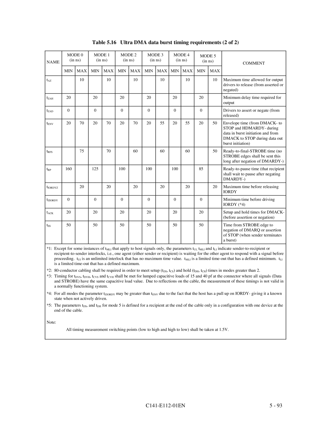
Table 5.16 Ultra DMA data burst timing requirements (2 of 2)
| MODE 0 | MODE 1 | MODE 2 | MODE 3 | MODE 4 | MODE 5 |
| ||||||
NAME | (in ns) | (in ns) | (in ns) | (in ns) | (in ns) | (in ns) | COMMENT | ||||||
|
|
|
|
|
|
|
|
|
| ||||
| MIN | MAX | MIN | MAX | MIN | MAX | MIN | MAX | MIN | MAX | MIN | MAX |
|
|
|
|
|
|
|
|
|
|
|
|
|
|
|
tAZ |
| 10 |
| 10 |
| 10 |
| 10 |
| 10 |
| 10 | Maximum time allowed for output |
|
|
|
|
|
|
|
|
|
|
|
|
| drivers to release (from asserted or |
|
|
|
|
|
|
|
|
|
|
|
|
| negated) |
|
|
|
|
|
|
|
|
|
|
|
|
|
|
tZAH | 20 |
| 20 |
| 20 |
| 20 |
| 20 |
| 20 |
| Minimum delay time required for |
|
|
|
|
|
|
|
|
|
|
|
|
| output |
|
|
|
|
|
|
|
|
|
|
|
|
|
|
tZAD | 0 |
| 0 |
| 0 |
| 0 |
| 0 |
| 0 |
| Drivers to assert or negate (from |
|
|
|
|
|
|
|
|
|
|
|
|
| released) |
|
|
|
|
|
|
|
|
|
|
|
|
|
|
tENV | 20 | 70 | 20 | 70 | 20 | 70 | 20 | 55 | 20 | 55 | 20 | 50 | Envelope time (from DMACK- to |
|
|
|
|
|
|
|
|
|
|
|
|
| STOP and HDMARDY- during |
|
|
|
|
|
|
|
|
|
|
|
|
| data in burst initiation and from |
|
|
|
|
|
|
|
|
|
|
|
|
| DMACK to STOP during data out |
|
|
|
|
|
|
|
|
|
|
|
|
| burst initiation) |
|
|
|
|
|
|
|
|
|
|
|
|
|
|
tRFS |
| 75 |
| 70 |
| 60 |
| 60 |
| 60 |
| 50 | |
|
|
|
|
|
|
|
|
|
|
|
|
| STROBE edges shall be sent this |
|
|
|
|
|
|
|
|
|
|
|
|
| long after negation of |
|
|
|
|
|
|
|
|
|
|
|
|
|
|
tRP | 160 |
| 125 |
| 100 |
| 100 |
| 100 |
| 85 |
| |
|
|
|
|
|
|
|
|
|
|
|
|
| shall wait to pause after negating |
|
|
|
|
|
|
|
|
|
|
|
|
| |
|
|
|
|
|
|
|
|
|
|
|
|
|
|
tIORDYZ |
| 20 |
| 20 |
| 20 |
| 20 |
| 20 |
| 20 | Maximum time before releasing |
|
|
|
|
|
|
|
|
|
|
|
|
| IORDY |
|
|
|
|
|
|
|
|
|
|
|
|
|
|
tZIORDY | 0 |
| 0 |
| 0 |
| 0 |
| 0 |
| 0 |
| Minimum time before driving |
|
|
|
|
|
|
|
|
|
|
|
|
| IORDY (*4) |
|
|
|
|
|
|
|
|
|
|
|
|
|
|
tACK | 20 |
| 20 |
| 20 |
| 20 |
| 20 |
| 20 |
| Setup and hold times for DMACK- |
|
|
|
|
|
|
|
|
|
|
|
|
| (before assertion or negation) |
|
|
|
|
|
|
|
|
|
|
|
|
|
|
tSS | 50 |
| 50 |
| 50 |
| 50 |
| 50 |
| 50 |
| Time from STROBE edge to |
|
|
|
|
|
|
|
|
|
|
|
|
| negation of DMARQ or assertion |
|
|
|
|
|
|
|
|
|
|
|
|
| of STOP (when sender terminates |
|
|
|
|
|
|
|
|
|
|
|
|
| a burst) |
|
|
|
|
|
|
|
|
|
|
|
|
|
|
*1: Except for some instances of tMLI that apply to host signals only, the parameters tUI, tMLI and tLI indicate
*2:
*3: Timing for tDVS, tDVH, tCVS and tCVH shall be met for lumped capacitive loads of 15 and 40 pf at the connector where all signals (Data and STROBE) have the same capacitive load value. Due to reflections on the cable, the measurement of these timings is not valid in a normally functioning system.
*4: For all modes the parameter tZIORDY may be greater than tENV due to the fact that the host has a pull up on IORDY- giving it a known state when not actively driven.
*5: The parameters tDS, and tDH for mode 5 is defined for a recipient at the end of the cable only in a configuration with one device at the end of the cable.
Note:
All timing measurement switching points (low to high and high to low) shall be taken at 1.5V.
| 5 - 93 |