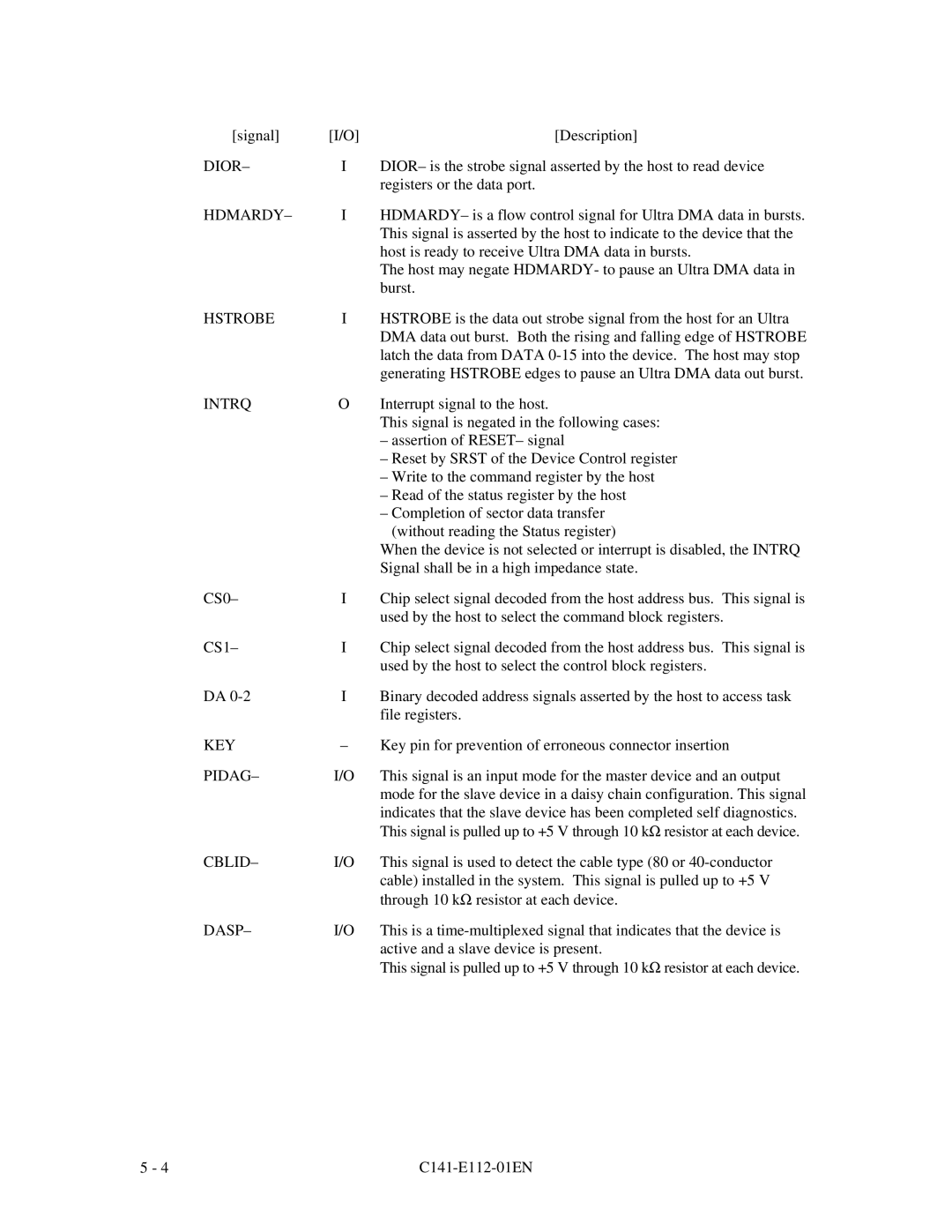
[signal] | [I/O] | [Description] |
DIOR– | I | DIOR– is the strobe signal asserted by the host to read device |
|
| registers or the data port. |
HDMARDY– | I | HDMARDY– is a flow control signal for Ultra DMA data in bursts. |
|
| This signal is asserted by the host to indicate to the device that the |
|
| host is ready to receive Ultra DMA data in bursts. |
|
| The host may negate HDMARDY- to pause an Ultra DMA data in |
|
| burst. |
HSTROBE | I | HSTROBE is the data out strobe signal from the host for an Ultra |
|
| DMA data out burst. Both the rising and falling edge of HSTROBE |
|
| latch the data from DATA |
|
| generating HSTROBE edges to pause an Ultra DMA data out burst. |
INTRQ | O | Interrupt signal to the host. |
|
| This signal is negated in the following cases: |
|
| – assertion of RESET– signal |
|
| – Reset by SRST of the Device Control register |
|
| – Write to the command register by the host |
|
| – Read of the status register by the host |
|
| – Completion of sector data transfer |
|
| (without reading the Status register) |
|
| When the device is not selected or interrupt is disabled, the INTRQ |
|
| Signal shall be in a high impedance state. |
CS0– | I | Chip select signal decoded from the host address bus. This signal is |
|
| used by the host to select the command block registers. |
CS1– | I | Chip select signal decoded from the host address bus. This signal is |
|
| used by the host to select the control block registers. |
DA | I | Binary decoded address signals asserted by the host to access task |
|
| file registers. |
KEY | – | Key pin for prevention of erroneous connector insertion |
PIDAG– | I/O | This signal is an input mode for the master device and an output |
|
| mode for the slave device in a daisy chain configuration. This signal |
|
| indicates that the slave device has been completed self diagnostics. |
|
| This signal is pulled up to +5 V through 10 kΩ resistor at each device. |
CBLID– | I/O | This signal is used to detect the cable type (80 or |
|
| cable) installed in the system. This signal is pulled up to +5 V |
|
| through 10 kΩ resistor at each device. |
DASP– | I/O | This is a |
|
| active and a slave device is present. |
|
| This signal is pulled up to +5 V through 10 kΩ resistor at each device. |
5 - 4 |
|