3.4.4Power supply connector (CN1)
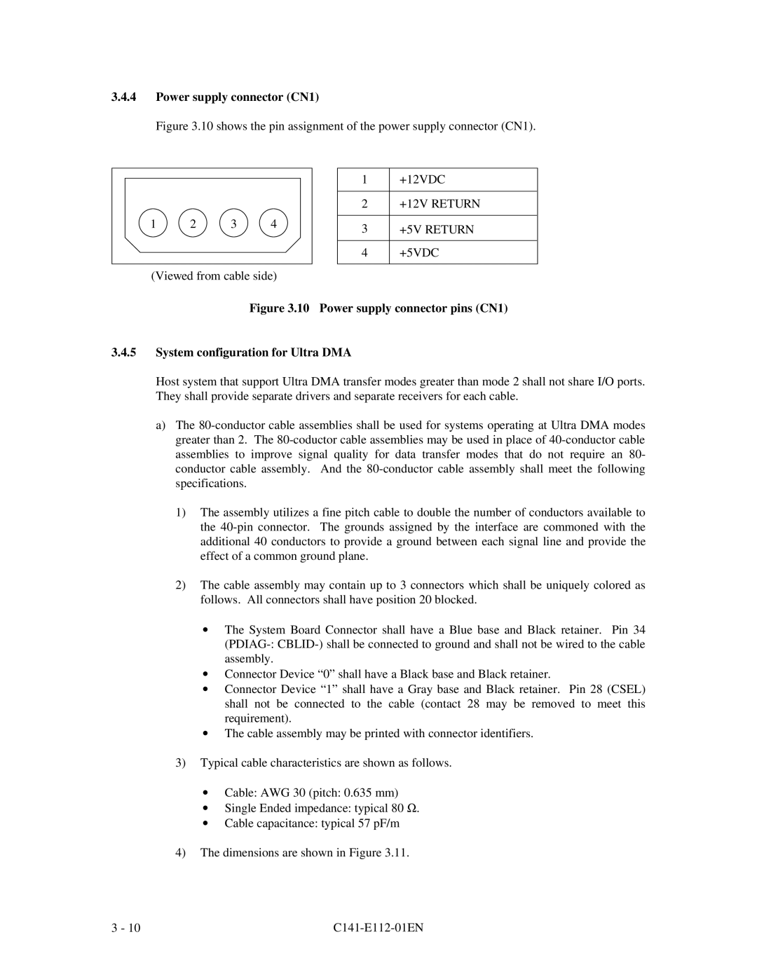
Figure 3.10 shows the pin assignment of the power supply connector (CN1).
1 | 2 | 3 | 4 |
(Viewed from cable side)
1+12VDC
2+12V RETURN
3+5V RETURN
4+5VDC
Figure 3.10 Power supply connector pins (CN1)
3.4.5System configuration for Ultra DMA
Host system that support Ultra DMA transfer modes greater than mode 2 shall not share I/O ports. They shall provide separate drivers and separate receivers for each cable.
a)The
1)The assembly utilizes a fine pitch cable to double the number of conductors available to the
2)The cable assembly may contain up to 3 connectors which shall be uniquely colored as follows. All connectors shall have position 20 blocked.
∙The System Board Connector shall have a Blue base and Black retainer. Pin 34
∙Connector Device “0” shall have a Black base and Black retainer.
∙Connector Device “1” shall have a Gray base and Black retainer. Pin 28 (CSEL) shall not be connected to the cable (contact 28 may be removed to meet this requirement).
∙The cable assembly may be printed with connector identifiers.
3)Typical cable characteristics are shown as follows.
∙Cable: AWG 30 (pitch: 0.635 mm)
∙Single Ended impedance: typical 80 Ω.
∙Cable capacitance: typical 57 pF/m
4)The dimensions are shown in Figure 3.11.
3 - 10 |
|