10.0) ASSEMBLY OF TUBE SECTIONS
CUT HAZARD
Sheet metal parts, particularly reflectors and vent have sharp edges. Always use gloves when handling.
Failure to do so may result in death, serious injury or property damage.
During field assembly of the heater body sections, the recommended procedure is as follows:
1.Before hanging heater sections, first determine the actual layout of the system (see Sections 7.0 & 8.0 for details). Consideration must also be taken for flue pipe, fresh air ducting, gas piping, clearances to combustibles, etc. before hanging heater. Typical suspension methods are shown in Section 9.0.
2.Hang each tube section individually. DO NOT attach the heater tube sections together on the ground and attempt to hang the entire system.
3.In all configurations, the burner box must be connected directly to either a) the
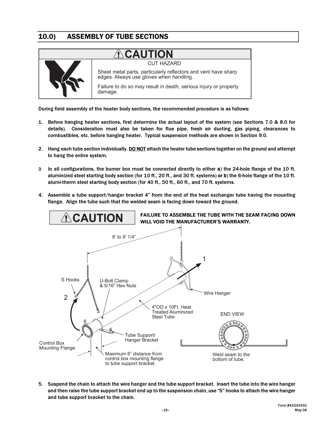
4.Assemble a tube support/hanger bracket 4” from the end of the heat exchanger tube having the mounting flange. Align the tube such that the welded seam is facing down toward the ground.
FAILURE TO ASSEMBLE THE TUBE WITH THE SEAM FACING DOWN
WILL VOID THE MANUFACTURER’S WARRANTY.
8’ to 9’ 1/4”
S Hooks
2
Control Box Mounting Flange
| 1 | |
| ||
& 5/16” Hex Nuts |
| |
| Wire Hanger | |
4"OD x 10Ft. Heat |
| |
Treated Aluminized | END VIEW | |
Steel Tube | ||
| ||
Tube Support/ |
| |
Hanger Bracket |
| |
Maximum 6” distance from | Weld seam to the | |
control box mounting flange | bottom of tube. | |
to tube support bracket. |
|
5.Suspend the chain to attach the wire hanger and the tube support bracket. Insert the tube into the wire hanger and then raise the tube support bracket end up to the suspension chain, use “S” hooks to attach the wire hanger and tube support bracket to the chain.
| Form #43343330 |
May 08 |