SINGLE HEATER VENTING (VERTICAL THROUGH THE ROOF)
1.When venting the heater to outside of building through a roof, use
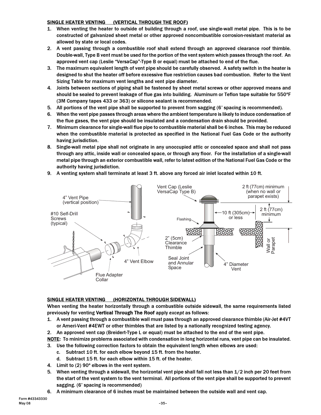
2.A vent passing through a combustible roof shall extend through an approved clearance roof thimble.
3.The maximum equivalent length of vent pipe should be carefully observed. A safety switch in the heater is designed to shut the heater off before excessive flue restriction causes bad combustion. Refer to the Vent Sizing Table for maximum vent lengths and vent pipe diameter.
4.Joints between sections of piping shall be fastened by sheet metal screws or other approved means and should be sealed to prevent leakage of flue gas into building. Aluminum or Teflon tape suitable for 550ºF (3M Company tapes 433 or 363) or silicone sealant is recommended.
5.All portions of the vent pipe shall be supported to prevent from sagging (6’ spacing is recommended).
6.When the vent pipe passes through areas where the ambient temperature is likely to induce condensation of the flue gases, the vent pipe should be insulated and a condensation drain should be provided.
7.Minimum clearance for
8.
9.A venting system shall terminate at least 3 ft. above any forced air inlet located within 10 ft.
Vent Cap (Leslie VersaCap Type B)
4” Vent Pipe (vertical position)![]()
#10
Screws![]() Flashing (typical)
Flashing (typical)
2” (5cm) ![]() Clearance Thimble
Clearance Thimble
Seal Joint
4” Vent Elbow and Annular
Space
Flue Adapter
Collar
|
|
|
|
|
|
| ||||||||||
|
|
| 2 ft (77cm) minimum |
|
| |||||||||||
|
| |||||||||||||||
|
|
|
| (when no wall or |
|
|
| |||||||||
|
|
|
| parapet exists) |
|
|
| |||||||||
|
|
|
|
|
|
|
|
|
|
|
|
|
|
|
|
|
|
|
|
|
|
|
|
|
|
|
|
|
|
|
|
|
|
|
|
|
|
|
|
|
|
|
|
|
|
|
|
|
|
|
|
|
|
|
|
|
|
|
|
|
|
| |||||
|
|
|
|
|
|
| 2 ft | (77cm) | ||||||||
|
| 10 ft (305cm) |
|
|
| minimum |
|
|
|
| ||||||
|
|
|
|
|
|
|
| |||||||||
|
| or less |
|
|
|
|
|
| ||||||||
|
|
|
|
|
|
|
|
|
|
|
|
|
|
| ||
|
|
|
|
|
|
|
|
|
|
|
|
|
| |||
|
|
|
|
|
|
|
|
|
|
|
|
|
|
|
| |
|
|
|
|
|
|
|
|
|
|
|
|
|
|
|
|
|
|
|
|
|
|
|
|
|
|
|
|
|
|
|
| ||
|
|
|
|
|
|
|
|
|
| |||||||
|
| 4” Diameter |
|
| Wall or Parapet |
|
| |||||||||
|
|
|
|
| ||||||||||||
|
|
|
|
|
|
|
|
|
|
|
| |||||
|
| Vent |
|
|
|
|
|
|
|
|
|
|
|
|
| |
SINGLE HEATER VENTING (HORIZONTAL THROUGH SIDEWALL)
When venting the heater horizontally through a combustible outside sidewall, the same requirements listed previously for venting Vertical Through The Roof apply except as follows:
1.A vent passing through a combustible wall must pass through an approved clearance thimble
2.An approved vent cap
NOTE: To minimize problems associated with condensation in long horizontal runs, vent pipe can be insulated.
3.Use the following correction factors to obtain the equivalent length when elbows are used:
c.Subtract 10 ft. for each elbow beyond 15 ft. from the heater.
d.Subtract 15 ft. for each elbow within 15 ft. of the heater.
4.Limit to (2) 90º elbows in the vent system.
5.When venting through a sidewall, the horizontal vent pipe shall fall not less than 1/2 inch per 20 feet from the start of the vent system to the vent terminal. All portions of the vent pipe shall be supported to prevent sagging. (6’ spacing is recommended)
6.A minimum clearance of 6 inches must be maintained between the outside wall and vent cap.
Form #43343330 |
|
May 08 |
