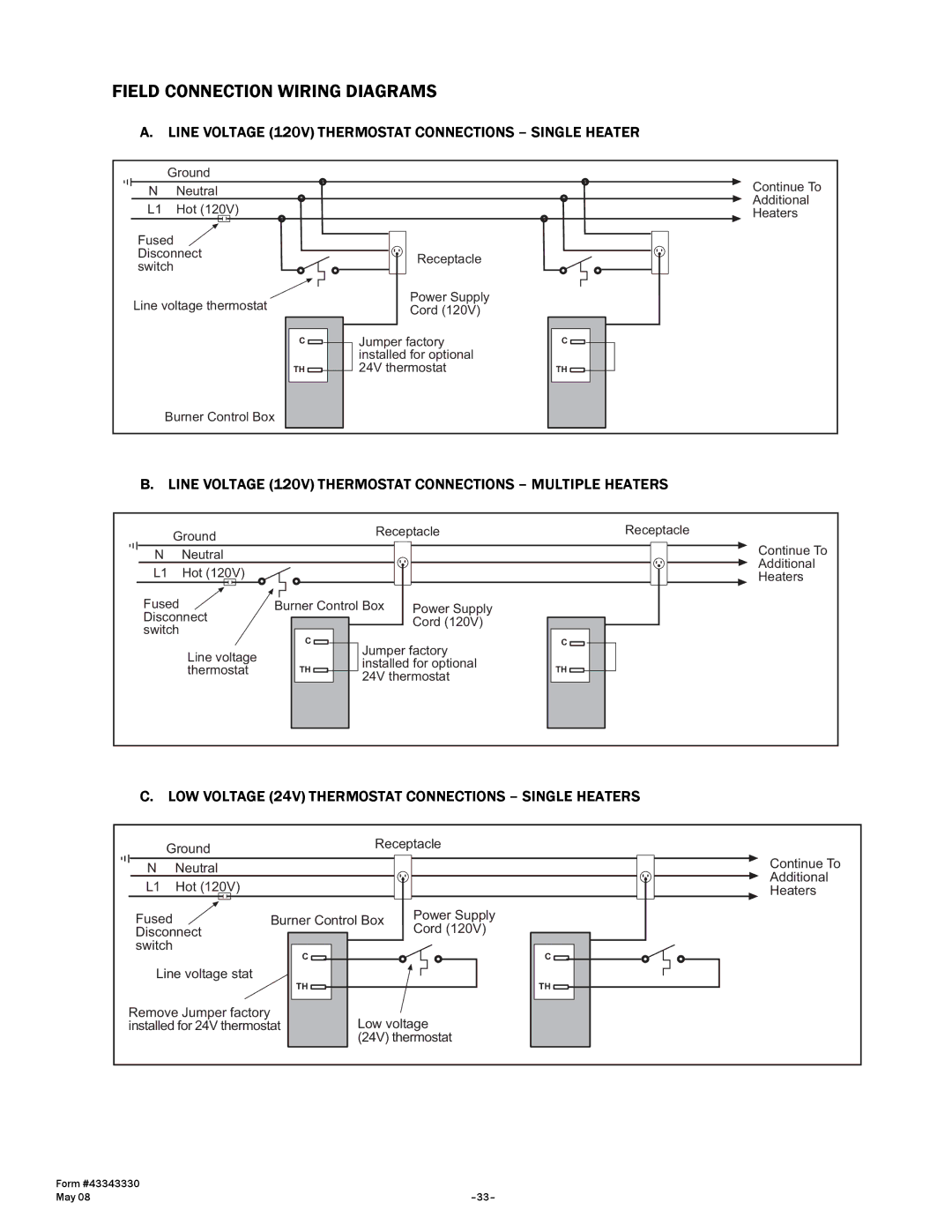
FIELD CONNECTION WIRING DIAGRAMS
A. LINE VOLTAGE (120V) THERMOSTAT CONNECTIONS – SINGLE HEATER
| Ground |
| Continue To |
N | Neutral |
| |
| Additional | ||
L1 | Hot (120V) |
| |
| Heaters | ||
Fused |
|
| |
Disconnect | Receptacle |
| |
switch |
| ||
|
| ||
Line voltage thermostat | Power Supply |
| |
Cord (120V) |
| ||
|
|
| |
| C | Jumper factory | C |
|
| installed for optional |
|
| TH | 24V thermostat | TH |
| Burner Control Box |
|
|
B. LINE VOLTAGE (120V) THERMOSTAT CONNECTIONS – MULTIPLE HEATERS
Ground |
| Receptacle | Receptacle | ||
|
|
| Continue To | ||
N | Neutral |
|
|
| |
|
|
| Additional | ||
L1 | Hot (120V) |
|
|
| |
|
|
| Heaters | ||
Fused |
| Burner Control Box | Power Supply |
| |
Disconnect |
|
| Cord (120V) |
| |
switch |
|
|
|
| |
| C |
|
|
| |
|
| Jumper factory | C | ||
| Line voltage |
|
| ||
|
| installed for optional |
| ||
| thermostat | TH | TH | ||
| 24V thermostat | ||||
|
|
|
| ||
C. LOW VOLTAGE (24V) THERMOSTAT CONNECTIONS – SINGLE HEATERS
Ground |
| Receptacle | ||
|
| Continue To | ||
N | Neutral |
|
| |
|
| Additional | ||
L1 | Hot (120V) |
|
| |
|
| Heaters | ||
Fused |
| Burner Control Box | Power Supply | |
Disconnect |
|
| Cord (120V) | |
switch |
| C |
| C |
|
|
| ||
Line voltage stat | TH |
| TH | |
|
|
| ||
Remove Jumper factory |
| Low voltage | ||
installed for 24V thermostat | ||||
|
|
| (24V) thermostat | |
Form #43343330 |
|
May 08 |