7.The horizontal venting system shall not terminate:
a.Less than 4 ft. (1.2m) below, 4 ft. (1.2m) horizontally from or 1 ft. (30cm) above any door, operable window or gravity air inlet into any building. The bottom of the vent terminal shall be located at least 7 ft. (2.1m) above grade or above snow accumulation level as determined by local codes.
b.Less than 3 ft. (0.9m) from a combustion air inlet.
c.Less than 3 ft. (0.9m) from any other building opening or any gas service regulator.
d.Less than 7 ft. (2.1m) above public walkways.
e.Directly over areas where condensate or vapor could create a nuisance or hazard or be harmful to the operation of gas utility meters, regulators, relief valves, or other equipment. Building materials should be protected from flue gases and condensate.
8.In regions of the country where prevailing winds are consistently higher than 40 mph, it may be necessary to terminate the vent system above the roof level.
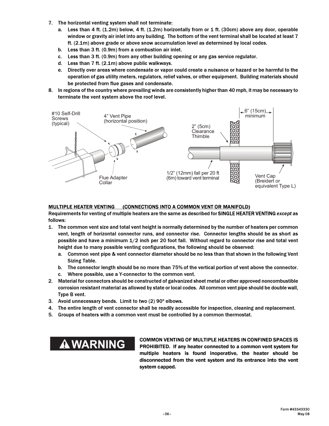
#10 | 4” Vent Pipe | |
Screws | ||
(horizontal position) | ||
(typical) | ||
|
Flue Adapter
Collar
2” (5cm) Clearance Thimble
1/2” (12mm) fall per 20 ft (6m) toward vent terminal
6” (15cm) minimum
Vent Cap (Breidert or equivalent Type L)
MULTIPLE HEATER VENTING (CONNECTIONS INTO A COMMON VENT OR MANIFOLD)
Requirements for venting of multiple heaters are the same as described for SINGLE HEATER VENTING except as follows:
1.The common vent size and total vent height is normally determined by the number of heaters per common vent, length of horizontal connector runs, and connector rise. Connector lengths should be as short as possible and have a minimum 1/2 inch per 20 foot fall. Without regard to connector rise and total vent height due to many possible venting configurations, the following should be observed:
a.Common vent pipe & vent connector diameter should be no less than that shown in the following Vent Sizing Table.
b.The connector length should be no more than 75% of the vertical portion of vent above the connector.
c.Where possible, use a
2.Material for connectors should be constructed of galvanized sheet metal or other approved noncombustible corrosion resistant material as allowed by state or local codes. All common vent pipe should be double wall, Type B vent.
3.Avoid unnecessary bends. Limit to two (2) 90º elbows.
4.The entire length of vent connector shall be readily accessible for inspection, cleaning and replacement.
5.Groups of heaters with a common vent must be controlled by a common thermostat.
COMMON VENTING OF MULTIPLE HEATERS IN CONFINED SPACES IS PROHIBITED. If any heater connected to a common vent system for multiple heaters is found inoperative, the heater should be disconnected from the vent system and its entrance into the vent system capped.
| Form #43343330 |
May 08 |