12.0) ATTACHING BURNER BOX ASSEMBLY
1.Attach the burner box and gasket to end of tube flange and secure with
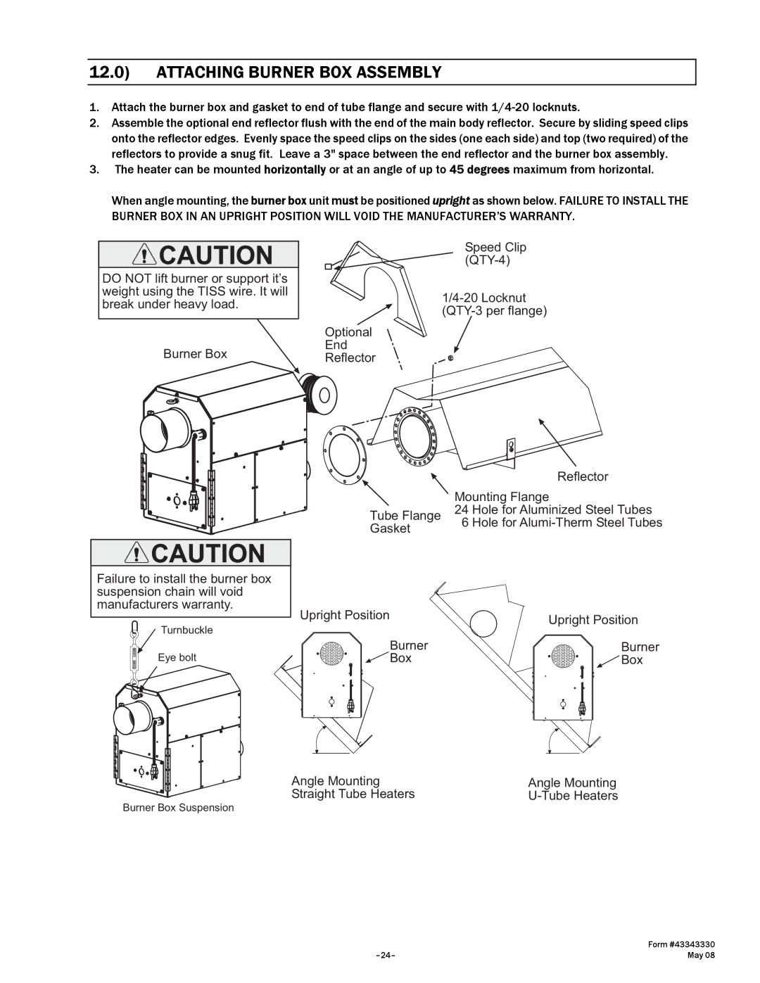
2.Assemble the optional end reflector flush with the end of the main body reflector. Secure by sliding speed clips onto the reflector edges. Evenly space the speed clips on the sides (one each side) and top (two required) of the reflectors to provide a snug fit. Leave a 3" space between the end reflector and the burner box assembly.
3.The heater can be mounted horizontally or at an angle of up to 45 degrees maximum from horizontal.
When angle mounting, the burner box unit must be positioned upright as shown below. FAILURE TO INSTALL THE BURNER BOX IN AN UPRIGHT POSITION WILL VOID THE MANUFACTURER’S WARRANTY.
DO NOT lift burner or support it’s weight using the TISS wire. It will break under heavy load.
Burner Box
Speed Clip
Optional
End
Reflector
|
| Reflector |
| Mounting Flange | |
Tube Flange | 24 | Hole for Aluminized Steel Tubes |
Gasket | 6 | Hole for |
|
| |
Failure to install the burner box |
|
|
suspension chain will void |
|
|
manufacturers warranty. | Upright Position |
|
| Upright Position | |
Turnbuckle |
| |
|
| |
| Burner | Burner |
Eye bolt | Box | Box |
Angle Mounting | Angle Mounting |
Straight Tube Heaters |
Burner Box Suspension
| Form #43343330 |
May 08 |