11.0) ADDING OPTIONAL 90º ELBOW (PTS ONLY)
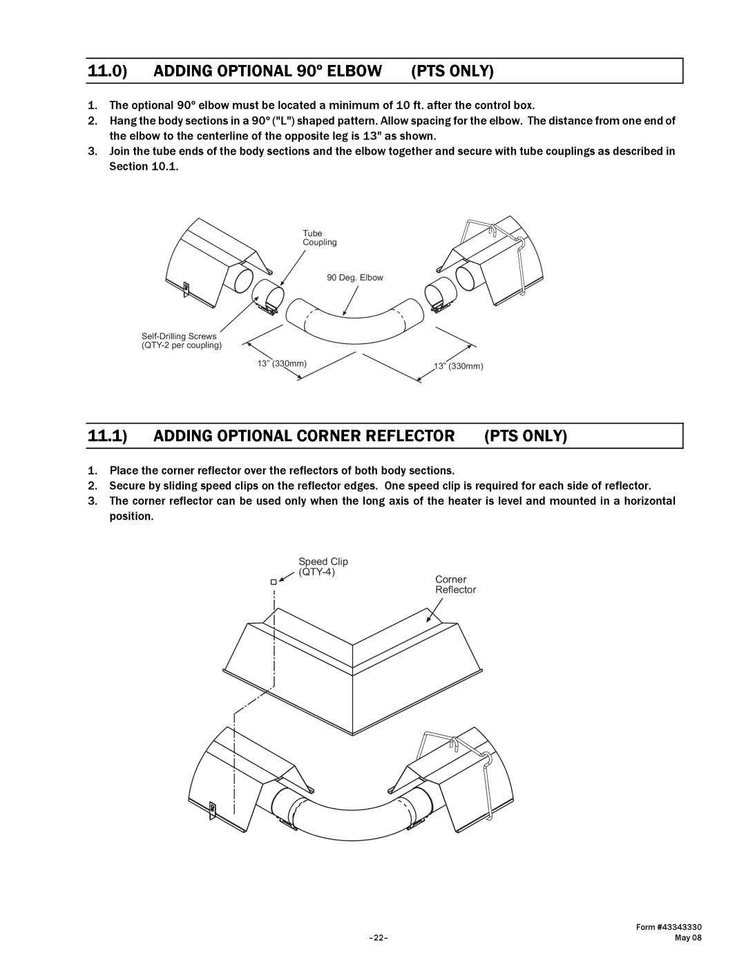
1.The optional 90º elbow must be located a minimum of 10 ft. after the control box.
2.Hang the body sections in a 90º ("L") shaped pattern. Allow spacing for the elbow. The distance from one end of the elbow to the centerline of the opposite leg is 13" as shown.
3.Join the tube ends of the body sections and the elbow together and secure with tube couplings as described in Section 10.1.
Tube
Coupling
90 Deg. Elbow
13” (330mm) | 13” (330mm) |
11.1) ADDING OPTIONAL CORNER REFLECTOR (PTS ONLY)
1.Place the corner reflector over the reflectors of both body sections.
2.Secure by sliding speed clips on the reflector edges. One speed clip is required for each side of reflector.
3.The corner reflector can be used only when the long axis of the heater is level and mounted in a horizontal position.
Speed Clip
Corner Reflector
| Form #43343330 |
May 08 |