KEY DIMENSIONS AND COMPONENTS OF THE GAS CONNECTIONS
Approved
Flexible Connector
14 to 17” | 2” (5cm) Max. | ||||
(36 to 43cm) | |||||
Displacement | |||||
|
|
| |||
|
|
|
|
| |
|
|
|
|
| |
* Available as Accessories
Gas Pressure
= 2 PSIG
Gas Supply
Piping
*Manual Gas
Shut Off Valve
Sediment Trap
(Drip Leg)
*Second Stage Regulator with Vent Leak Limiter to reduce the Supply Pressure below 14” W.C.
Burner Movement
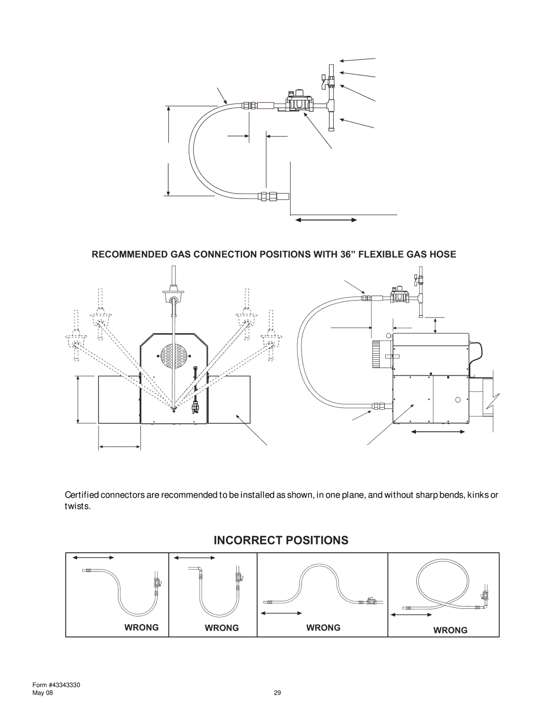
RECOMMENDED GAS CONNECTION POSITIONS WITH 36” FLEXIBLE GAS HOSE
Alternate Positions
7 5/8”
6”
DO NOT install gas connector
vertically if fresh air is to be Adaptor 1/2” NPT male connected.
3 7/8” (10cm)
| Adaptor 1/2” NPT female |
| Gas pipe work must not restrict |
END VIEW | opening of hinged service doors. |
|
Minimum 1” (25cm)
Burner Movement
SIDE VIEW
Certified connectors are recommended to be installed as shown, in one plane, and without sharp bends, kinks or twists.
INCORRECT POSITIONS
MovementMovement
WRONG |
| Movement | Movement |
WRONG | WRONG | WRONG |
Form #43343330 |
|
May 08 |