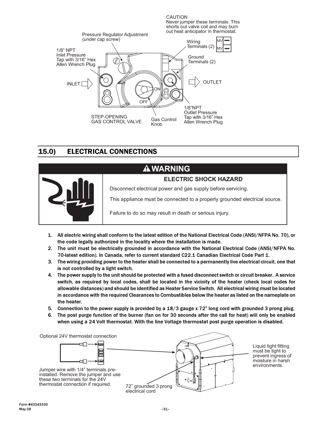
Pressure Regulator Adjustment (under cap screw)
1/8” NPT Inlet Pressure
Tap with 3/16” Hex Allen Wrench Plug
INLET ![]()
OFF
STEP-OPENING
GAS CONTROL VALVE
CAUTION
Never jumper these terminals. This shorts out valve coil and may burn out heat anticipator in thermostat.
Wiring MV
Terminals (2) MV
| Ground | |
| Terminals (2) | |
| OUTLET | |
ON |
| |
| 1/8”NPT | |
| Outlet Pressure | |
Gas Control | Tap with 3/16” Hex | |
Allen Wrench Plug | ||
Knob | ||
|
15.0) ELECTRICAL CONNECTIONS
ELECTRIC SHOCK HAZARD
Disconnect electrical power and gas supply before servicing.
This appliance must be connected to a properly grounded electrical source.
Failure to do so may result in death or serious injury.
1.All electric wiring shall conform to the latest edition of the National Electrical Code (ANSI/NFPA No. 70), or the code legally authorized in the locality where the installation is made.
2.The unit must be electrically grounded in accordance with the National Electrical Code (ANSI/NFPA No.
3.The wiring providing power to the heater shall be connected to a permanently live electrical circuit, one that is not controlled by a light switch.
4.The power supply to the unit should be protected with a fused disconnect switch or circuit breaker. A service switch, as required by local codes, shall be located in the vicinity of the heater (check local codes for allowable distances) and should be identified as Heater Service Switch. All electrical wiring must be located in accordance with the required Clearances to Combustibles below the heater as listed on the nameplate on the heater.
5.Connection to the power supply is provided by a 18/3 gauge x 72” long cord with grounded 3 prong plug.
6.The post purge function of the burner (fan on for 30 seconds after the call for heat) will only be enabled when using a 24 Volt thermostat. With the line Voltage thermostat post purge operation is disabled.
Optional 24V thermostat connection
Jumper wire with 1/4” terminals pre- installed. Remove the jumper and use these two terminals for the 24V
Liquid tight fitting must be tight to prevent ingress of moisture in harsh environments.
thermostat connection if required. 72” grounded 3 prong electrical cord
Form #43343330 |
|
May 08 |