GE Energy
3.6IRIG-B Input Adapter
The IRIG-B Input Adapter (GE Part No. 520-0211) plugs into a dedicated IRIG-B slot (slot 9) on the D400. The IRIG-B Input card accepts an IRIG-B signal in one of three input formats through a corresponding connector type:
•Modulated IRIG-B through a BNC connector J2
•Demodulated IRIG-B (TTL) through a terminal block TB1
•Fiber Optic through a Receive (RX) 820-850 nm ST connector U12
The IRIG-B signal (TTL) can be subsequently distributed to attached IEDs through one of the following output methods:
•IRIG-B Distribution Adapter (GE Part No. 520-0212). See section “3.7 IRIG-B Distribution Adapter”
•RS-232 Adapter (GE Part No. 520-0207). See section “3.3 RS-232 Adapter”
•On-board fiber optic output (TX) on 820-850 nm ST connector U13
See section “4.6 IRIG-B Connections” for wiring instructions.
Configuration Options
The input signal formats and output options are selectable via three switches on the IRIG- B Input card:
•IRIG-B state option is configured by switch SW1
•Input signal format is configured by switch SW2
•Fiber optic TX option is configured by switch SW3
Follow instructions for setting the switches to select the appropriate IRIG-B signal formats and functions.
Factory Default
The factory default setting is the Standard state on each channel.
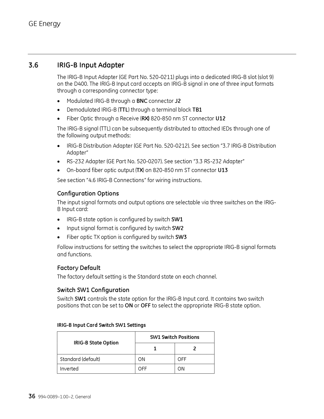
Switch SW1 Configuration
Switch SW1 controls the state option for the IRIG-B Input card. It contains two switch positions that can be set to ON or OFF to select the appropriate IRIG-B state option.
IRIG-B Input Card Switch SW1 Settings
| IRIG-B State Option | SW1 Switch Positions |
| | |
| 1 | 2 |
| |
| | | |
| Standard (default) | ON | OFF |
| | | |
| Inverted | OFF | ON |
| | | |