GE Energy
Power Source | Connection |
|
|
|
| Wiring Diagram | |||||
|
|
|
|
|
|
|
| ||||
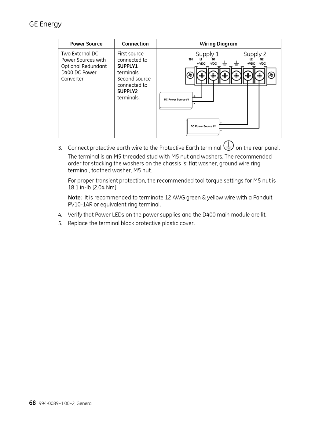
Two External DC | First source |
|
|
|
| Supply 1 | Supply 2 | ||||
Power Sources with | connected to |
|
|
|
|
|
|
|
|
|
|
Optional Redundant | SUPPLY1 |
|
|
|
|
|
|
|
|
|
|
D400 DC Power | terminals. |
|
|
|
|
|
|
|
|
|
|
Converter | Second source |
|
|
|
|
|
|
|
|
|
|
| connected to |
|
|
|
|
|
|
|
|
|
|
| SUPPLY2 |
|
|
|
| + |
|
|
|
|
|
| terminals. |
| DC Power Source #1 |
|
|
|
|
|
| ||
|
|
|
|
|
|
|
|
| |||
|
|
|
|
|
| - |
|
|
|
|
|
|
|
|
|
|
|
|
|
| + |
|
|
|
|
|
|
| DC Power Source #2 |
|
| ||||
|
|
|
|
|
|
|
| ||||
|
|
|
|
|
|
|
|
| - |
|
|
|
|
|
|
|
|
|
|
|
|
|
|
3.Connect protective earth wire to the Protective Earth terminal ![]() on the rear panel.
on the rear panel.
The terminal is an M5 threaded stud with M5 nut and washers. The recommended order for stacking the washers on the chassis is: flat washer, ground wire ring terminal, toothed washer, M5 nut.
For proper transient protection, the recommended tool torque settings for M5 nut is 18.1
Note: It is recommended to terminate 12 AWG green & yellow wire with a Panduit
4.Verify that Power LEDs on the power supplies and the D400 main module are lit.
5.Replace the terminal block protective plastic cover.
68
