Alarm Relay Output
The alarm relay output is activated when an alarm condition exists. The alarm output is only active for the duration of the alarm.
Alarm relays can be programmed in the menu system to respond to macros, and video loss. See section 3.11 for information about configuring the alarms in the menu system.
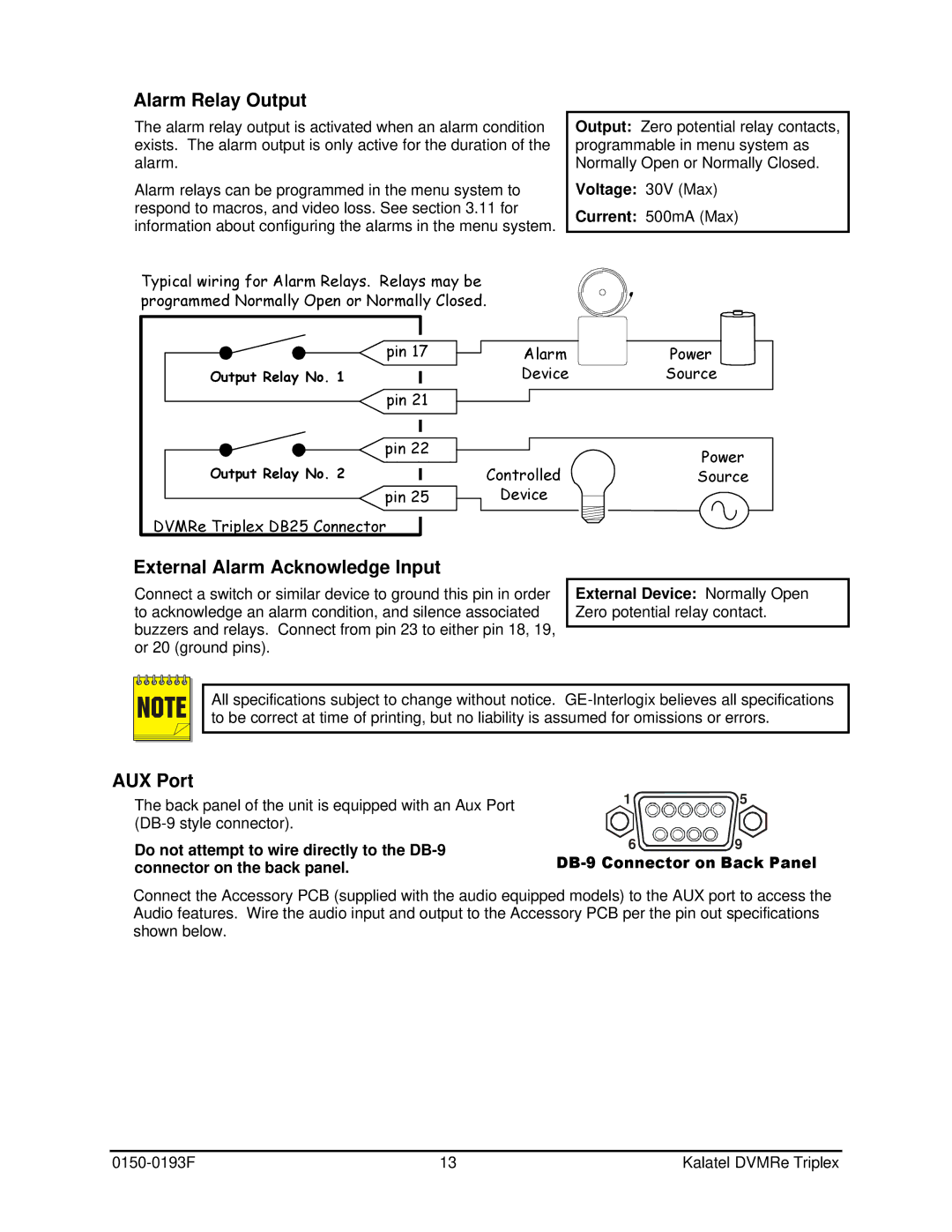
Typical wiring for Alarm Relays. Relays may be programmed Normally Open or Normally Closed.
Output: Zero potential relay contacts, programmable in menu system as Normally Open or Normally Closed.
Voltage: 30V (Max)
Current: 500mA (Max)
pin 17
Output Relay No. 1
pin 21
Alarm | Power |
Device | Source |
pin 22
Output Relay No. 2
pin 25
DVMRe Triplex DB25 Connector
Power
ControlledSource
Device
External Alarm Acknowledge Input
Connect a switch or similar device to ground this pin in order to acknowledge an alarm condition, and silence associated buzzers and relays. Connect from pin 23 to either pin 18, 19, or 20 (ground pins).
External Device: Normally Open Zero potential relay contact.
NOTE | All specifications subject to change without notice. | ||
to be correct at time of printing, but no liability is assumed for omissions or errors. | |||
|
|
|
|
|
|
|
|
|
|
|
|
|
|
|
|
AUX Port
The back panel of the unit is equipped with an Aux Port
Do not attempt to wire directly to the
1 ![]()
![]()
![]() 5
5
6 ![]()
![]() 9
9
Connect the Accessory PCB (supplied with the audio equipped models) to the AUX port to access the Audio features. Wire the audio input and output to the Accessory PCB per the pin out specifications shown below.
13 | Kalatel DVMRe Triplex |