STATIONARY EMERGENCY GENERATOR INSTALLATION
~
k..Connecting this generator to an electrical illsystem normally supplied by an electric util- ity shall be by means of a transfer switch
(such as the "GTS" type transfer switch), so as to isolate the electric system from the utility distribution system when the genera- tor is operating. Failure to isolate the electric system by these means will result in damage to the generator and may also result in injury or death to utility workers due to backfeed of electrical energy.
ACAUTIONI
t If an open bottom is used, the
materials and should be located such that combustible materials are not capable of accumulating under the generator set.
Only qualified, competent installation contractors or electricians thoroughly familiar with applicable codes, standards and regula- tions should install this stationary emergency electric power sys- tem. The installation must comply strictly with all codes, standards and regulations pertaining to the installation.
This genset must be installed on a level surface. The base frame must be level within two (2) inches all around.
ACAUTIONI
AAfter the system has been installed, do noth-
..... ing that might render the installation in non· compliance with such codes, standards and regulations.
NOTE:
For more information about the installation of a stationary emergency system, order
NFPA STANDARDS
The following published standards booklets pertaining to station- ary emergency electric systems are available from the National Fire Protection Association (NFPA), Batterymarch Park, Quincy, MA 02269 or www.nfpa.org.
oNFPA No. 37, STATIONARY COMBUSTION ENGINES AND GAS TURBINES.
o NFPA No. 76A, ESSENTIAL ELECTRICAL SYSTEMS FOR HEALTH CARE FACILITIES.
oNFPA No. 220, STANDARD TYPES OF BUILDING CONSTRUCTION o NFPA No. 68, GUIDE FOR EXPLOSION VENTING
o NFPA No. 70, NATIONAL ELECTRICAL CODE.
Installation
•NFPA No. 30, FLAMMABLE AND COMBUSTIBLE LIQUIDS CODE.
•NFPA No. 10, INSTALLATION, MAINTENANCE AND USE OF PORTABLE FIRE EXTINGUISHERS.
OTHER PUBLISHED STANDARDS
In addition to NFPA standards, the following information pertain- ing to the installation and use of stationary emergency electric systems is available:
•Article X, NATIONAL BUILDING CODE, available from the American Insurance Association, 85 John Street, New York, NY 10038,
oAGRICULTURAL WIRING HANDBOOK, obtainable from the Food and Energy Council, 909 University Avenue, Columbia, MO, 65201.
•ASAE
•A52.1, AMERICAN NATIONAL STANDARD FOR CHIMNEYS, FIREPLACES AND VENTING SYSTEMS, available from the American National Standard Institute, 1430 Broadway, New York, N.Y 10018.
BASIC STATIONARY EMERGENCY ELECTRIC SYSTEM
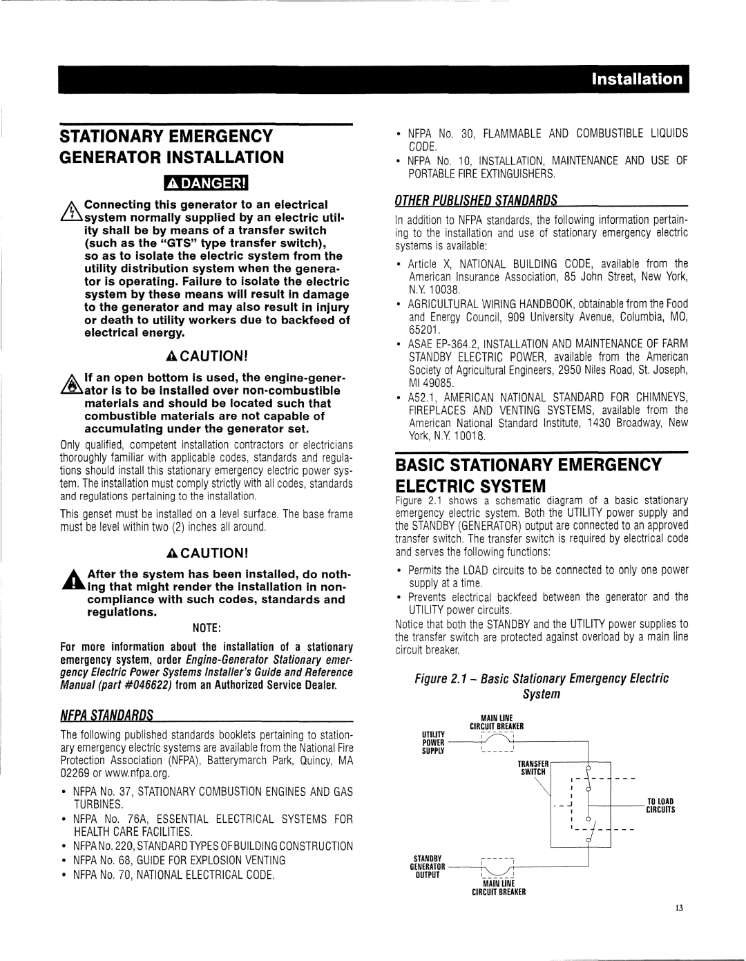
Figure 2.1 shows a schematic diagram of a basic stationary emergency electric system. Both the UTILITY power supply and the STANDBY (GENERATOR) output are connected to an approved transfer switch. The transfer switch is required by electrical code and serves the following functions:
oPermits the LOAD circuits to be connected to only one power supply at atime.
oPrevents electrical backfeed between the generator and the UTILITY power circuits.
Notice that both the STANDBY and the UTILITY power supplies to the transfer switch are protected against overload by a main line circuit breaker.
Figure 2.1 - Basic Stationary Emergency Electric
System
MAIN UNE
CIRCUIT BREAKER
UTIUTY
POWER
SUPPLY '- - -
TRANSFER
SWITCH
| I - |
|
| , |
|
| I |
|
. _ J | , | TO LOAD |
| ||
| , |
|
| '- - |
|
STANDBY |
| ||
GENERATOR | |||
OUTPUT | , | ~ |
|
MAIN UNE
CIRCUIT BREAKER
13
