Operation
Fuel System
Make sure the fuel supply system to the generator (a) delivers the correct fuel at the correct pressure and (b) is properly purged and leak tested according to code. No fuel leakage is permitted. See "Specifications" for more information
If the unit has been idle for along period of time, or if the fuel lines or system components have been removed and reinstalled, the fuel system may require bleeding to remove air from the system. Air in the fuel system causes hard starting and rough operation. All fuel system lines must be installed and must be tight A loose line may show no sign of leakage, but may draw air into the system.
ACAUTIONI
AUse a suitable container to catch the fuel
.... that will spill during system bleeding pro- cess. Clean up all spilled fuel after bleeding.
Generator Set Lubrication
Check the engine crankcase oil level befol'eoperating and add oil to the proper level - the dipstick "FULL'mark. Never operate the engine with the oil level below the dipstick "ADD" mark. See "Specifications" and "Engine Oil Recommendations"
Check the oil level in the generator gearbox (if so equipped) prior to initial use and at the intervals indicated by the" Service Schedule." The recommended oil is SAE 90 gear lubricant
Also, if the engine is equipped with a mechanical governor, make sure the governor is properly lubricated with clean engine oil.
Engine Coolant
Have the engine cooling system properly filled with the recom- mended coolant mixture. Check the system for leaks and other problems. See "Specifications" and "Coolant"
Belt Tension
Check the engine fan belt tension and condition prior to placing the unit into service and at recommended intervals. Belt tension is correct when aforce of approximately 22 pounds (10 kg), applied midway between pulleys, deflects the belt about 3/8- to
Electrical System
Make sure the generator is properly connected to an approved earth ground.
Make sure the generator battery is fUlly charged, properly installed and interconnected, and ready for use.
Check to ensure that there are no loose electrical connections, Restrain any loose wires to keep them clear of any moving genera- tor set components.
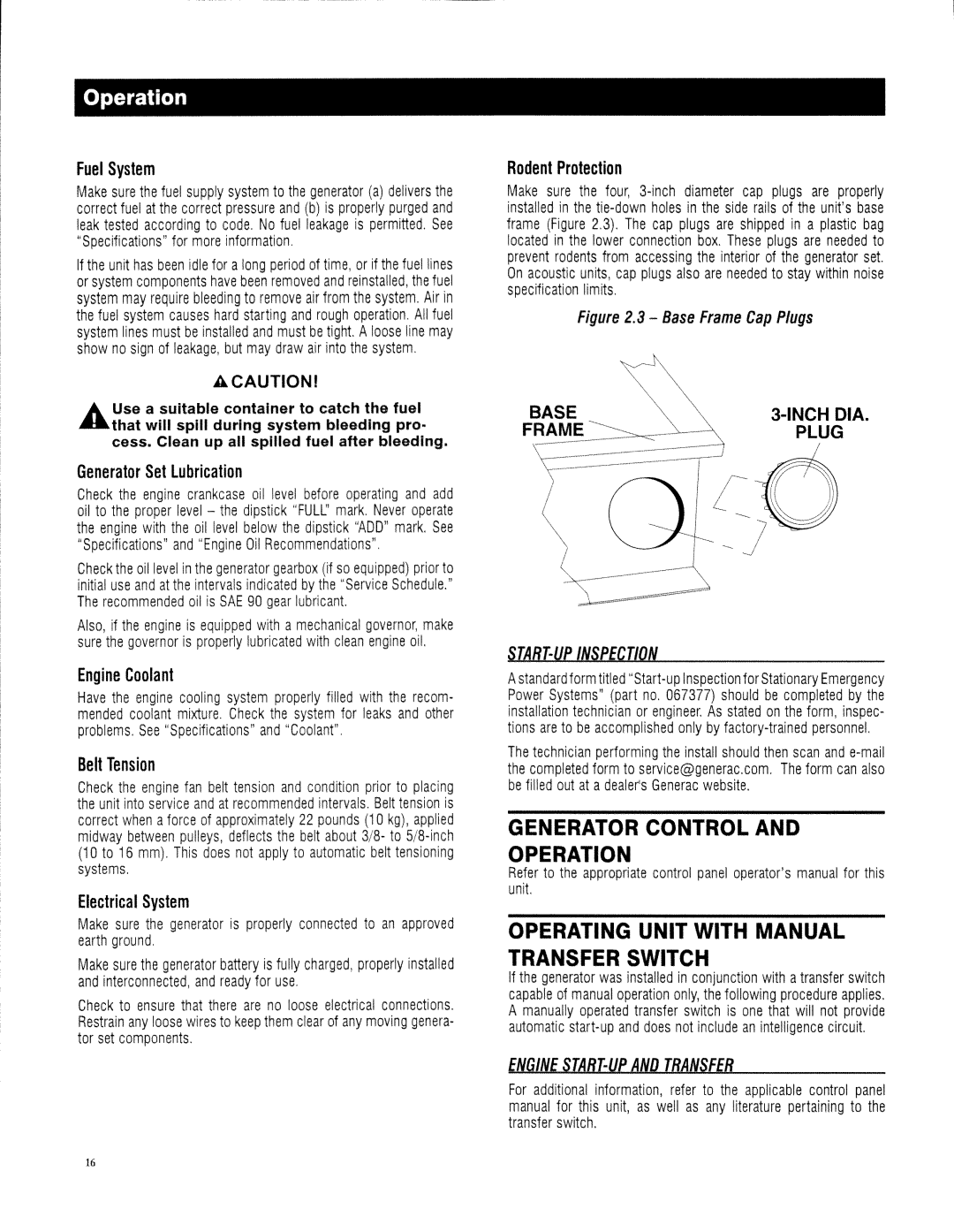
Rodent Protection
Make sure the four,
Figure 2.3 - Base Frame Cap Plugs
BASE | |
FRAME | PLUG |
STA8r-UP INSPECTION
Astandard form titled
The technician performing the install should then scan and
GENERATOR CONTROL AND OPERATION
Refer to the appropriate control panel operator'smanual for this unit
OPERATING UNIT WITH MANUAL TRANSFER SWITCH
If the generator was installed in conjunction with atransfer switch capable of manual operation only, the following procedure applies. A manually operated transfer switch is one that will not provide automatic
ENGINE STA8T-UP AND TRANSFE8
For additional information, refer to the applicable control panel manual for this unit, as well as any literature pertaining to the transfer switch.
16