FUEL SYSTEM REDUIREMENTS AND RECOMMENDATIONS
Diesel Fuel System: See Chapter 8 of
1.Beginning October 1, 2007, owners and operators that use diesel fuel must use diesel fuel that meets:
A.Sulfur content of 500 parts per million (ppm) maximum.
B.Cetane index or aromatic content as follows:
•A minimum cetane index of 40 or;
•A maximum aromatic content of 35 volume percent.
2.Beginning October 1, 2010, owners and operators that use diesel fuel must use diesel fuel that meets:
A.Sulfur content of 15 parts per million (ppm) maximum.
B.Cetane index or aromatic content as follows:
•A minimum cetane index of 40 or;
•A maximum aromatic content of 35 volume percent.
BATTERY INSTALLATION
When a unit is supplied with out a battery or during replacement use the following table to properly select the battery size and mini- mum Cold Cranking Ampere required for a particular unit.
Diesel Engine | Battery Size | Minimum CCA | |
2.4L | GRP 27 or GRP 31 | 650 or 925 | |
3.4L | |||
|
| ||
4.5L | GRP 31 or GRP | 925 | |
31E | |||
|
| ||
6.7L (100, 130Kw) | 1 or 2 X GRP 31 | 925 | |
6.7L (150, 175Kw) | 2 X GRP 31 | 925 | |
8.7L | |||
|
| ||
10.3L |
|
| |
12.9L |
|
| |
13.0L | 2 x GRP 31 or 2 x | 925 or 1155 | |
16.0L | GRP 80 | ||
| |||
18.0L |
|
| |
22.0L |
|
|
Fill the battery with the proper electrolyte fluid if necessary and have the battery fUlly charged before installing it.
General Information
Before installing and connecting the battery, complete the follow- ing steps:
1.Set the generator'sAUTO/OFF/MANUAL switch to OFF.
2.Turn off utility power supply to the transfer switch.
3.Remove the 10A and 15A fuses from the generator control panel.
Battery cables were factory connected at the generator (Figure
1.4). Connect cables to battery posts as follows:
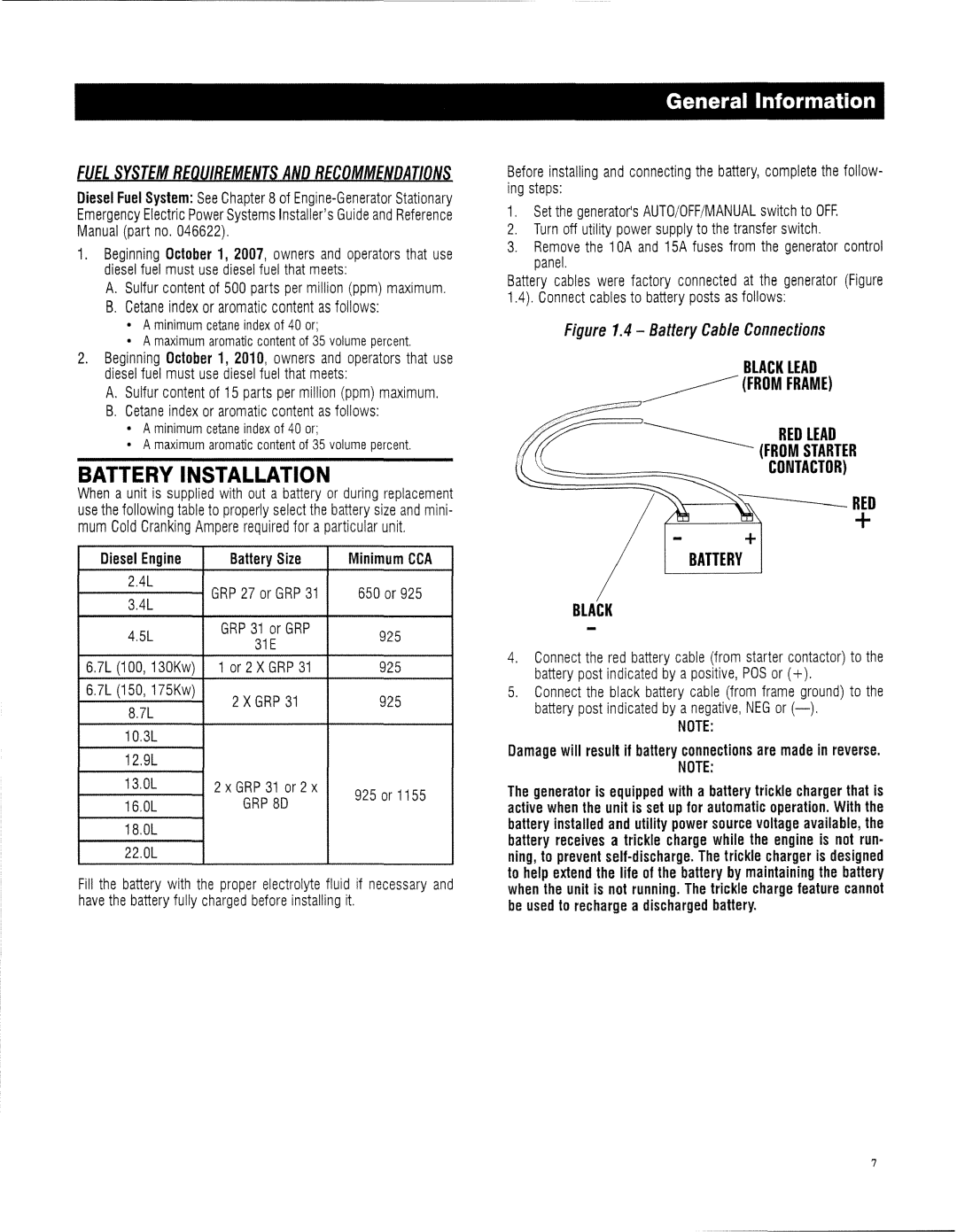
Figure 1.4 - Battery Cable Connections
BLACK LEAD
~(FROM FRAME)
___________ RED LEAD
(FROM STARTER
CONTACTOR)
+
BATTERY
BLACK
4.Connect the red battery cable (from starter contactor) to the battery post indicated by a positive, pas or (+).
5.Connect the black battery cable (from frame ground) to the battery post indicated by anegative, NEG or
NOTE:
Damage will result if battery connections are made in reverse.
NOTE:
The generator is equipped with a battery trickle charger that is active when the unit is set up for automatic operation. With the battery installed and utility power source voltage available, the battery receives a trickle charge while the engine is not run- ning, to prevent
7