English
KB_MS
COMA | |
| LPT1 |
COMB | |
_OUT |
|
LINE _IN | GAME |
_IN LINE | |
MIC |
|
USB | LAN |
AC97
CPU FAN | PWR FAN |
ATX_12V |
|
| Pro |
|
|
| / |
|
| SOCKET478 | Ultra2 |
F_AUDIO |
| ||
|
| ||
|
|
| |
CD_IN |
|
|
|
|
| Intel 845PE |
|
2X_DET |
|
| |
|
| AGP | |
|
| ||
P4 Titan667 | PCI1 |
| |
SPDIF_O |
| PCI2 |
|
|
|
| |
AUX_IN |
| PCI3 BATTERY |
|
SPDIF_IN |
| PCI4 |
|
|
| PDC20276** |
|
RAM_LED | FLOPPY |
ATX |
IDE2 | IDE1 |
SYS_FANCLR_PWD
DDR1 | DDR2 | DDR3 |
ICH4
| CI | SCR | |
MAIN | BACKUP | IR/CIR | |
BIOS | BIOS | ||
|
SUR_CEN | PCI5 | IDE4** |
| ||
|
| IDE3** |
ITE8712 | PCI6 | SIL3112A** |
| ||
|
| |
CNR** |
|
|
| F_USB1 | F_USB2 |
S_ATA1**
S_ATA2**
PWR_LED
F_PANEL
WOL
Serial ATA**
Front USB 2.0
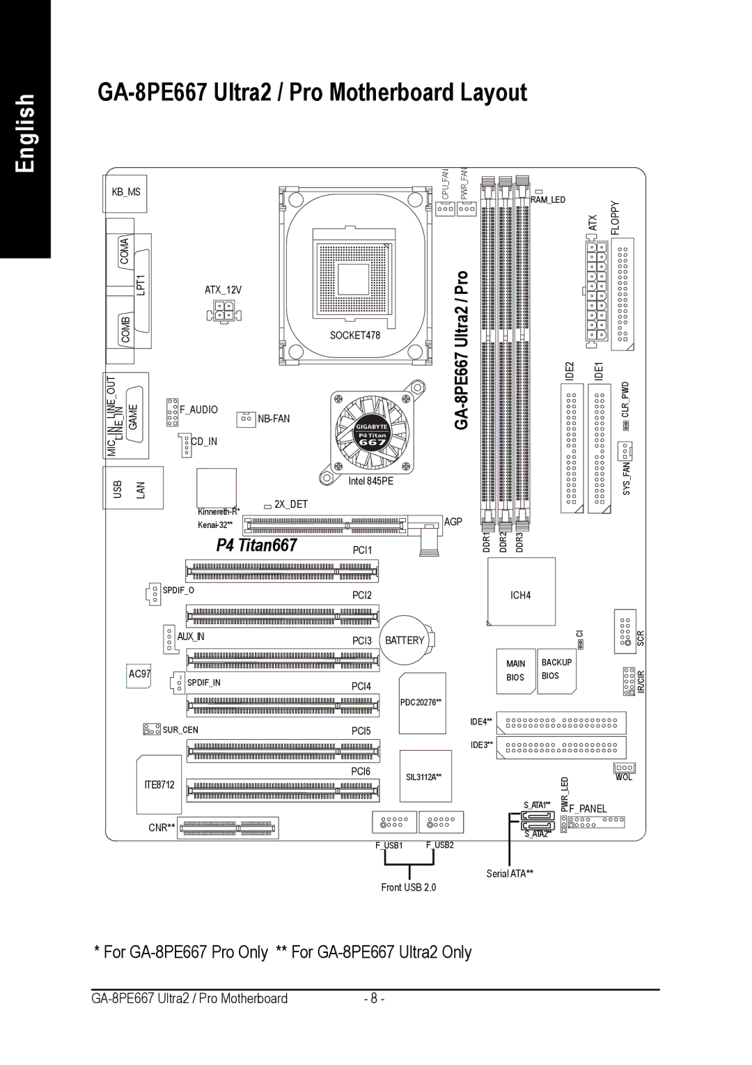
* For
- 8 - |