Knife Setting Jig Method: Both tables are low- ered to fit the jig on the cutterhead, as shown in Figure 47, and the knife heights are set to just touch the middle pad of the jig.
The knife setting jig makes it easy to ensure that the knives project out of the cutterhead evenly. After using the knife setting jig to set the knives, you have to
Figure 47. Using knife setting jig to set knife
height.
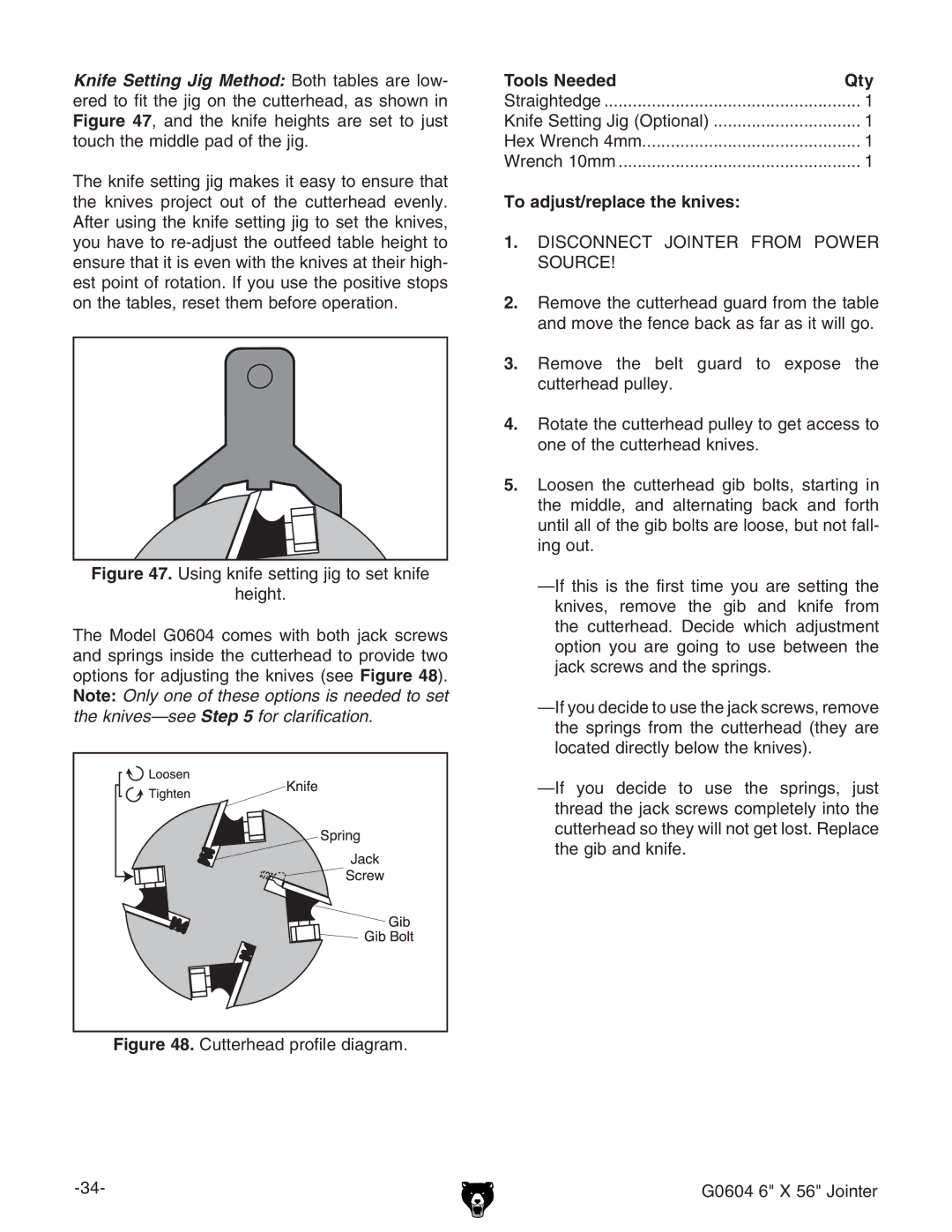
The Model G0604 comes with both jack screws and springs inside the cutterhead to provide two options for adjusting the knives (see Figure 48). Note: Only one of these options is needed to set the knives—see Step 5 for clarification.
Figure 48. Cutterhead profile diagram.
Tools Needed | Qty |
Straightedge | 1 |
Knife Setting Jig (Optional) | 1 |
Hex Wrench 4mm | 1 |
Wrench 10mm | 1 |
To adjust/replace the knives: |
|
1.DISCONNECT JOINTER FROM POWER SOURCE!
2.Remove the cutterhead guard from the table and move the fence back as far as it will go.
3.Remove the belt guard to expose the cutterhead pulley.
4.Rotate the cutterhead pulley to get access to one of the cutterhead knives.
5.Loosen the cutterhead gib bolts, starting in the middle, and alternating back and forth until all of the gib bolts are loose, but not fall- ing out.
G0604 6" X 56" Jointer |