Meter Roll 2 Speed Display
•Set the speed of the metering roll when the two speed automatic moisture control feature of the dryer is utilized.
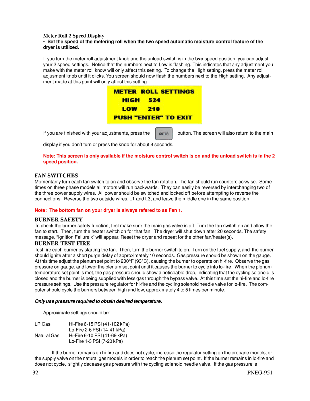
If you turn the meter roll adjustment knob and the unload switch is in the two speed position, you can adjust your 2 speed settings. Notice that the numbers next to Low is flashing. This indicates that any adjustment you make with the meter roll know will only affect this setting. To change the High setting, press the meter roll adjusment knob until it clicks. You screen should now flash the numbers next to the High setting. Any adjust- ment made at this point will only affect this setting.
If you are finished with your adjustments, press the | button. The screen will also return to the main |
display if you don’t turn or press the knob for about 8 seconds.
Note: This screen is only available if the moisture control switch is on and the unload switch is in the 2 speed position.
FAN SWITCHES
Momentarily turn each fan switch to on and observe the fan rotation. The fan should run counterclockwise. Some- times on three phase models all motors will run backwards. They can easily be reversed by interchanging two of the three power supply wires. All power should be switched and locked off before attempting to reverse the connections. Reverse the two outside wires, L1 and L3, and leave the middle one in the same position.
Note: The bottom fan on your dryer is always refered to as Fan 1.
BURNER SAFETY
To check the burner safety function, first make sure the main gas valve is off. Turn the fan switch on and allow the fan to start. Then, turn the heater switch on for that fan. The dryer will shut down after 20 seconds. The safety message, “Ignition Failure x” will appear. Reset the dryer and repeat for the other fan/heater(s).
BURNER TEST FIRE
Test fire each burner by starting the fan. Then, turn the burner switch to on. Turn on the fuel supply, and the burner should ignite after a short purge delay of approximately 10 seconds. Gas pressure should be shown on the gauge. At this time adjust the plenum set point to 200°F (93°C), causing the burner to operate on
Only use pressure required to obtain desired temperature.
Approximate settings should be:
LP Gas | |
| |
Natural Gas | |
|
If the burner remains on
32 |
|