The transformer: Two things can cause failure: the first is shorting the leads during the installation, or letting the strands touch at the terminal on the control board. The second is a static charge (generally associated with a lightning storm or power outage); use of a surge protector will help.
Testing the battery: This is a 12 volt 7 Ah battery. The proper way to test this is to perform a load test. Place the voltmeter on D.C.; put the red probe on the (+) positive terminal and place the black probe on
Note: A loose battery terminal will cause the same symptoms that a bad battery will cause. Terminals should be secure and corrosion free.
Remote control range: This will vary at each installation. (see FCC disclaimer on page 23), but generally varies from 50 ft. to 100 ft.
•Make sure that the receiver is located above metal fences.
•Moving the receiver even a few inches can change the range of operation.
•Move the receiver as far from the motor as possible to avoid the chance of electrical interference.
•Check or change the battery in the transmitter.
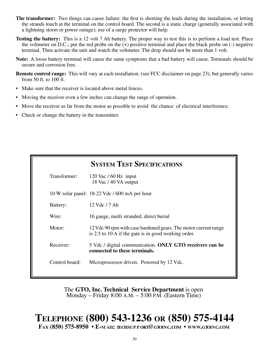
| SYSTEM TEST SPECIFICATIONS |
Transformer: | 120 Vac / 60 Hz input |
| 18 Vac / 40 VA output |
10 W solar panel: | |
Battery: | 12 Vdc / 7 Ah |
Wire: | 16 gauge, multi stranded, direct burial |
Motor: | 12 Vdc 90 rpm with case hardened gears. The motor current range |
| is 2.5 to 10 A if the gate is in good working order. |
Receiver: | 5 Vdc / digital communication. ONLY GTO receivers can be |
| connected to these terminals. |
Control board: | Microprocessor driven. Powered by 12 Vdc. |
The GTO, Inc. Technical Service Department is open
Monday – Friday 8:00 A.M. – 5:00 P.M. (Eastern Time)
TELEPHONE (800) 543-1236 OR (850) 575-4144
FAX (850)
30
