POWERING THE SYSTEM
CONNECTING THE BATTERY
OFF |
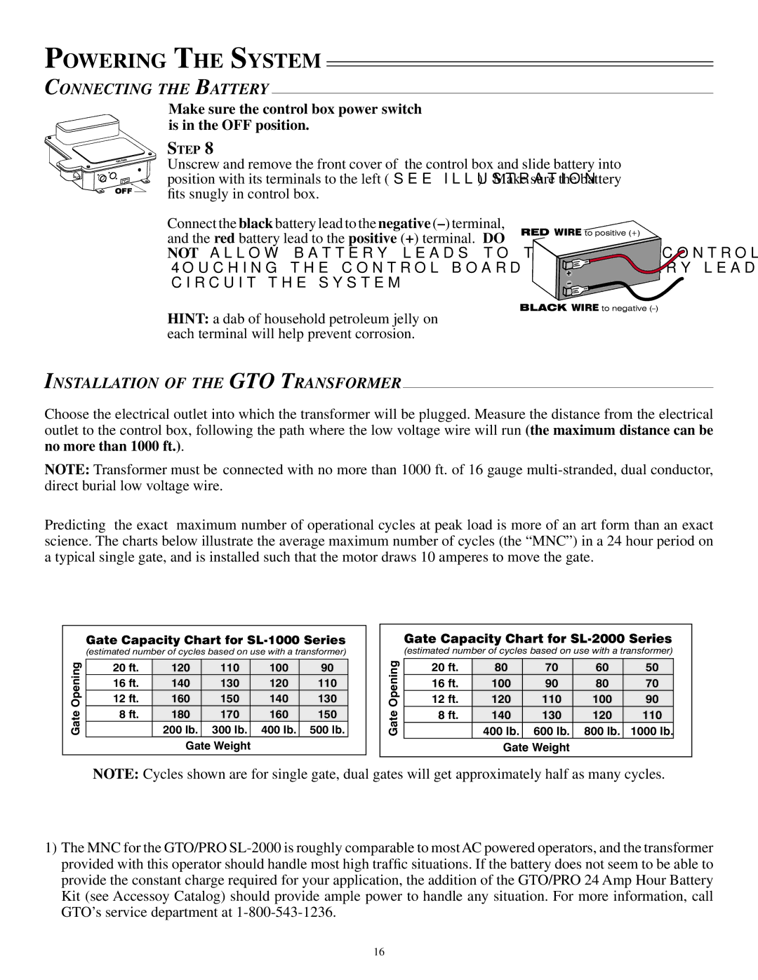
Make sure the control box power switch is in the OFF position.
STEP 8
Unscrew and remove the front cover of the control box and slide battery into position with its terminals to the left (see illustration). Make sure the battery fits snugly in control box.
Connect the black battery lead to the negative
HINT: a dab of household petroleum jelly on each terminal will help prevent corrosion.
RED WIRE to positive (+)
BLACK WIRE to negative
INSTALLATION OF THE GTO TRANSFORMER
Choose the electrical outlet into which the transformer will be plugged. Measure the distance from the electrical outlet to the control box, following the path where the low voltage wire will run (the maximum distance can be
no more than 1000 ft.).
NOTE: Transformer must be connected with no more than 1000 ft. of 16 gauge
Predicting the exact maximum number of operational cycles at peak load is more of an art form than an exact science. The charts below illustrate the average maximum number of cycles (the “MNC”) in a 24 hour period on a typical single gate, and is installed such that the motor draws 10 amperes to move the gate.
Gate Opening
Gate Capacity Chart for SL-1000 Series
(estimated number of cycles based on use with a transformer)
20 ft. | 120 | 110 | 100 | 90 |
16 ft. | 140 | 130 | 120 | 110 |
12 ft. | 160 | 150 | 140 | 130 |
8 ft. | 180 | 170 | 160 | 150 |
200 lb. 300 lb. 400 lb. 500 lb.
Gate Weight
Gate Opening
Gate Capacity Chart for SL-2000 Series
(estimated number of cycles based on use with a transformer)
20 ft. | 80 | 70 | 60 | 50 |
16 ft. | 100 | 90 | 80 | 70 |
12 ft. | 120 | 110 | 100 | 90 |
8 ft. | 140 | 130 | 120 | 110 |
400 lb. 600 lb. | 800 lb. 1000 lb. |
Gate Weight |
|
NOTE: Cycles shown are for single gate, dual gates will get approximately half as many cycles.
1)The MNC for the GTO/PRO
16