PARTS IDENTIFICATION
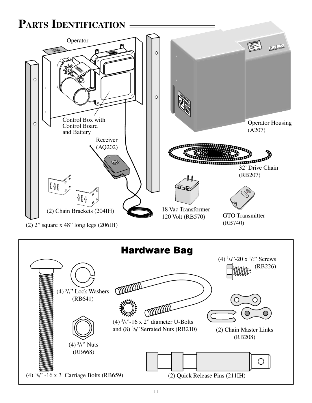
Operator
Control Box with Control Board and Battery
Receiver (AQ202)
(2) Chain Brackets (204IH)
(2) 2” square x 48” long legs (206IH)
![]() Operator Housing (A207)
Operator Housing (A207)
32’ Drive Chain (RB207)
18 Vac Transformer
120 Volt (RB570) GTO Transmitter
(RB740)
![]() (4) 3/8” Lock Washers
(4) 3/8” Lock Washers ![]() (RB641)
(RB641)
(4)
(4) 3/8” Nuts
(RB668)
(4) ![]() (RB226)
(RB226)
(2)Chain Master Links (RB208)
(4) 3/8” | (2) Quick Release Pins (211IH) |
11