WIRING THE SECOND OPERATOR
When the units are set in place and you have completed wiring the first unit follow the instructions below.
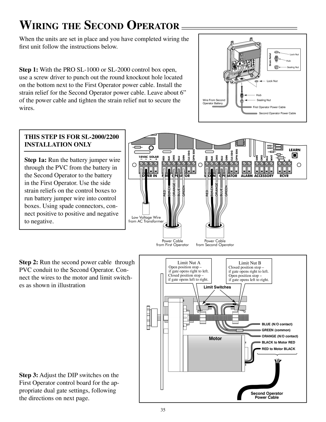
Step 1: With the PRO
| Relief | Lock Nut |
|
| |
| Strain | Hub |
| Sealing Nut | |
|
| |
| Lock Nut |
|
| Hub |
|
Wire From Second | Sealing Nut |
|
Operator Battery
First Operator Power Cable
Second Operator Power Cable
THIS STEP IS FOR SL-2000/2200
INSTALLATION ONLY
Step 1a: Run the battery jumper wire through the PVC from the battery in the Second Operator to the battery in the First Operator. Use the side strain reliefs on the control boxes to run battery jumper wire into control boxes. Using spade connectors, con- nect positive to positive and negative
18VAC SOLAR ~ ~ – +
POWER IN |
RED BLK ORG BLU GRN CLS EDG | OPN EDG |
FIRST OPERATOR |
|
GREEN
BLUE
ORANGE
BLACK
RED
RED BLK ORG BLU GRN CLS EDG OPN EDG |
SECOND OPERATOR |
GREEN
BLUE
ORANGE
BLACK
RED
SEQ1 | ON |
|
|
SEQ2 |
| LEARN | |
|
|
|
GRN ORG | BLU | WHT | R | B G |
|
|
| ||
ALARM ACCESSORY |
| RCVR | ||
to negative.
Low Voltage Wire from AC Transformer
Step 2: Run the second power cable through PVC conduit to the Second Operator. Con- nect the wires to the motor and limit switch- es as shown in illustration
Step 3: Adjust the DIP switches on the First Operator control board for the ap- propriate dual gate settings, following the directions on next page.
|
|
|
|
|
|
Power Cable | Power Cable | ||||
from First Operator | from Second Operator | ||||
Limit Nut A | Limit Nut B |
Open position stop – | Closed position stop – |
if gate opens right to left. | if gate opens right to left. |
Closed position stop – | Open position stop – |
if gate opens left to right. | if gate opens left to right. |
Limit Switches
| BLUE (N/O contact) | |
| GREEN (common) | |
Motor | ORANGE (N/O contact) | |
BLACK to Motor RED | ||
| ||
| RED to Motor BLACK |
Second Operator
Power Cable
35