3654 Portable H2/N2 Analyzer - Installation | 13 of 66 |
|
|
1.7 Flow Chamber Installation
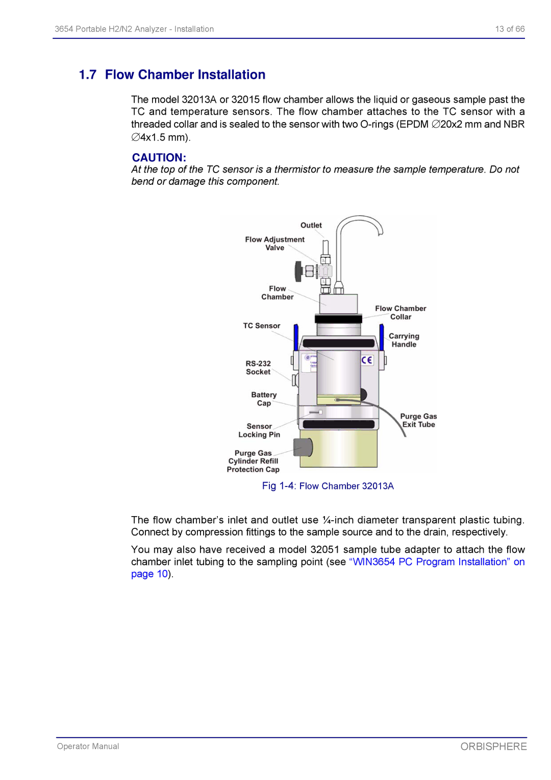
The model 32013A or 32015 flow chamber allows the liquid or gaseous sample past the TC and temperature sensors. The flow chamber attaches to the TC sensor with a threaded collar and is sealed to the sensor with two
CAUTION:
At the top of the TC sensor is a thermistor to measure the sample temperature. Do not bend or damage this component.
Fig
The flow chamber’s inlet and outlet use
You may also have received a model 32051 sample tube adapter to attach the flow chamber inlet tubing to the sampling point (see “WIN3654 PC Program Installation” on page 10).
Operator Manual | ORBISPHERE |