|
| RCV56HCF PCI/CardBus Modem Designer’s Guide | |
|
|
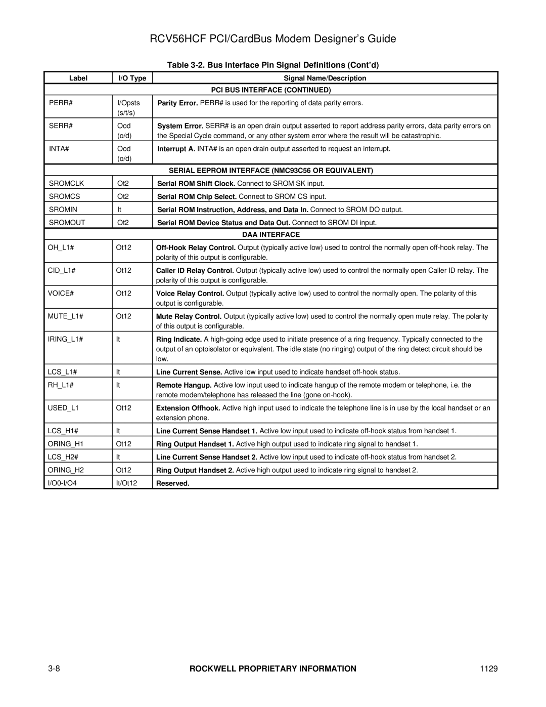
| Table |
|
|
|
|
Label | I/O Type |
| Signal Name/Description |
|
|
| PCI BUS INTERFACE (CONTINUED) |
PERR# | I/Opsts |
| Parity Error. PERR# is used for the reporting of data parity errors. |
| (s/t/s) |
|
|
|
|
|
|
SERR# | Ood |
| System Error. SERR# is an open drain output asserted to report address parity errors, data parity errors on |
| (o/d) |
| the Special Cycle command, or any other system error where the result will be catastrophic. |
|
|
|
|
INTA# | Ood |
| Interrupt A. INTA# is an open drain output asserted to request an interrupt. |
| (o/d) |
|
|
|
|
| SERIAL EEPROM INTERFACE (NMC93C56 OR EQUIVALENT) |
SROMCLK | Ot2 |
| Serial ROM Shift Clock. Connect to SROM SK input. |
SROMCS | Ot2 |
| Serial ROM Chip Select. Connect to SROM CS input. |
SROMIN | It |
| Serial ROM Instruction, Address, and Data In. Connect to SROM DO output. |
SROMOUT | Ot2 |
| Serial ROM Device Status and Data Out. Connect to SROM DI input. |
|
|
| DAA INTERFACE |
OH_L1# | Ot12 |
| |
|
|
| polarity of this output is configurable. |
|
|
|
|
CID_L1# | Ot12 |
| Caller ID Relay Control. Output (typically active low) used to control the normally open Caller ID relay. The |
|
|
| polarity of this output is configurable. |
|
|
|
|
VOICE# | Ot12 |
| Voice Relay Control. Output (typically active low) used to control the normally open. The polarity of this |
|
|
| output is configurable. |
MUTE_L1# | Ot12 |
| Mute Relay Control. Output (typically active low) used to control the normally open mute relay. The polarity |
|
|
| of this output is configurable. |
IRING_L1# | It |
| Ring Indicate. A |
|
|
| output of an optoisolator or equivalent. The idle state (no ringing) output of the ring detect circuit should be |
|
|
| low. |
LCS_L1# | It |
| Line Current Sense. Active low input used to indicate handset |
RH_L1# | It |
| Remote Hangup. Active low input used to indicate hangup of the remote modem or telephone, i.e. the |
|
|
| remote modem/telephone has released the line (gone |
USED_L1 | Ot12 |
| Extension Offhook. Active high input used to indicate the telephone line is in use by the local handset or an |
|
|
| extension phone. |
LCS_H1# | It |
| Line Current Sense Handset 1. Active low input used to indicate |
ORING_H1 | Ot12 |
| Ring Output Handset 1. Active high output used to indicate ring signal to handset 1. |
LCS_H2# | It |
| Line Current Sense Handset 2. Active low input used to indicate |
ORING_H2 | Ot12 |
| Ring Output Handset 2. Active high output used to indicate ring signal to handset 2. |
It/Ot12 |
| Reserved. | |
ROCKWELL PROPRIETARY INFORMATION | 1129 |