RCV56HCF PCI/CardBus Modem Designer’s Guide
10.Minimize the number of
11.Keep all signal traces away from crystal circuits.
12.Distribute high frequency signals continuously on a single trace rather than several traces radiating from one point.
13.Provide adequate clearance (e.g., 60 mil minimum) around feedthroughs in any internal planes in the DAA circuit.
14.Eliminate ground loops, which are unexpected current return paths to the power source.
4.1.4 Power
1.Identify digital power (VDD) and analog power (AVDD) supply connections.
2.Place a 10 µF electrolytic or tantalum capacitor in parallel with a ceramic 0.1 µF capacitor between power and ground at one or more points in the digital section. Place one set nearest to where power enters the PCB (edge connector or power connector) and place another set at the furthest distance from where power enters the PCB. These capacitors help to supply current surge demands by the digital circuits and prevent those surges from generating noise on the power lines that may affect other circuits.
3.For
4.Generally, route all power traces before signal traces.
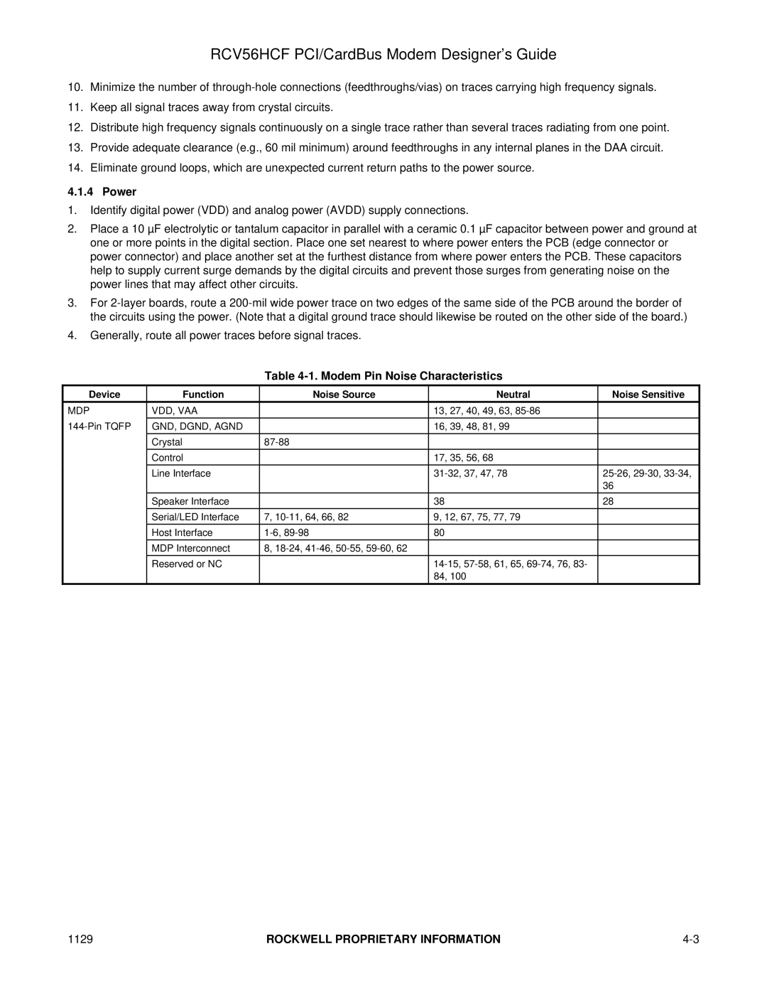
Table 4-1. Modem Pin Noise Characteristics
Device | Function | Noise Source | Neutral | Noise Sensitive |
MDP | VDD, VAA |
| 13, 27, 40, 49, 63, |
|
GND, DGND, AGND |
| 16, 39, 48, 81, 99 |
| |
|
|
|
|
|
| Crystal |
|
| |
| Control |
| 17, 35, 56, 68 |
|
| Line Interface |
| ||
|
|
|
| 36 |
|
|
|
|
|
| Speaker Interface |
| 38 | 28 |
| Serial/LED Interface | 7, | 9, 12, 67, 75, 77, 79 |
|
| Host Interface | 80 |
| |
|
|
|
|
|
| MDP Interconnect | 8, |
|
|
| Reserved or NC |
|
| |
|
|
| 84, 100 |
|
1129 | ROCKWELL PROPRIETARY INFORMATION |