RCV56HCF PCI/CardBus Modem Designer’s Guide
3.3 INTERFACE TIMING AND WAVEFORMS
3.3.1 PCI Bus Timing
The PCI interface timing conforms to the PCI Local Bus Specification, Production Version, Revision 2.1, June 1, 1995.
3.3.2 Serial EEPROM Timing
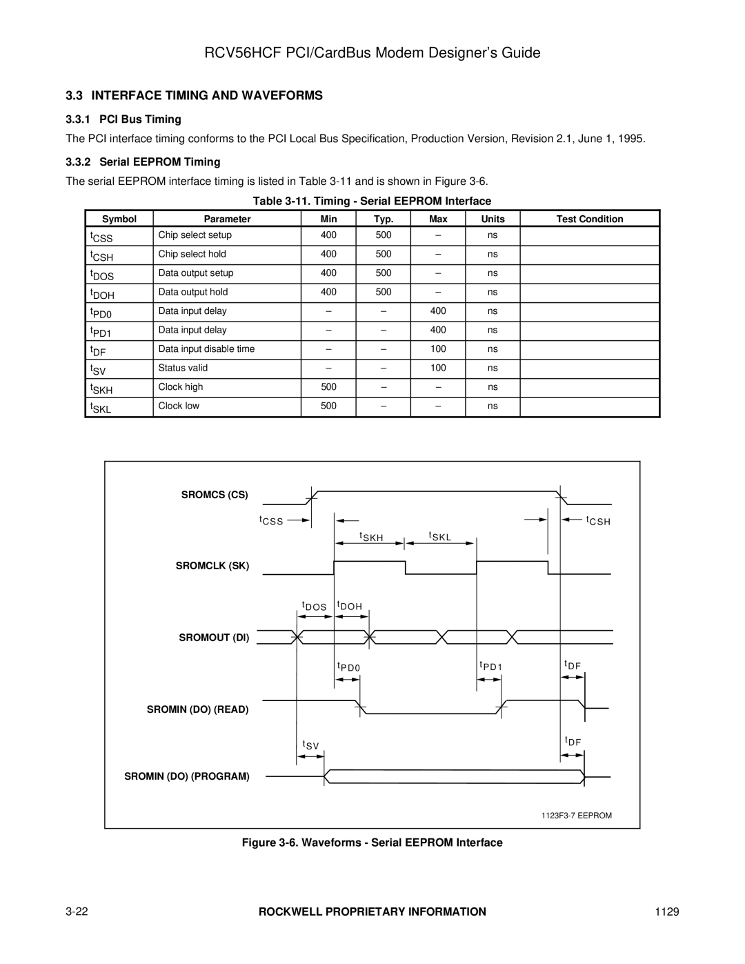
The serial EEPROM interface timing is listed in Table
Table 3-11. Timing - Serial EEPROM Interface
Symbol | Parameter | Min | Typ. | Max | Units | Test Condition |
tCSS | Chip select setup | 400 | 500 | – | ns |
|
tCSH | Chip select hold | 400 | 500 | – | ns |
|
tDOS | Data output setup | 400 | 500 | – | ns |
|
tDOH | Data output hold | 400 | 500 | – | ns |
|
tPD0 | Data input delay | – | – | 400 | ns |
|
tPD1 | Data input delay | – | – | 400 | ns |
|
tDF | Data input disable time | – | – | 100 | ns |
|
tSV | Status valid | – | – | 100 | ns |
|
tSKH | Clock high | 500 | – | – | ns |
|
tSKL | Clock low | 500 | – | – | ns |
|
SROMCS (CS)
t C S S
SROMCLK (SK)
t D O S
SROMOUT (DI)
SROMIN (DO) (READ)
t S V
t S K H
tD O H
t P D 0
t S K L
t P D 1
![]() t C S H
t C S H
tD F
t D F
SROMIN (DO) (PROGRAM)
Figure 3-6. Waveforms - Serial EEPROM Interface
ROCKWELL PROPRIETARY INFORMATION | 1129 |
