RCV56HCF PCI/CardBus Modem Designer’s Guide
5.3 SERIAL EEPROM INTERFACE
The serial EEPROM interface is used to load PCI configuration parameters and CIS information (required for Card Bus operation) after a reset occurs. The PCI configuration information to be loaded requires 10 bytes of data. The CIS information requires 384 bytes of data. The minimum serial EEPROM size is 512 bytes (4096 bits). After the PCI reset signal is negated, the configuration data is read from the serial EEPROM and stored in the PCI configuration registers as required, then the CIS information is read from the serial EEPROM and stored in the internal RAM of the BIF. While the serial EEPROM data is being read and is being loaded in the configuration registers and the CIS RAM, any PCI access that occurs will receive a RETRY signal from the BIF device. After completion of the serial EEPROM reads, the BIF device will accept PCI transactions.
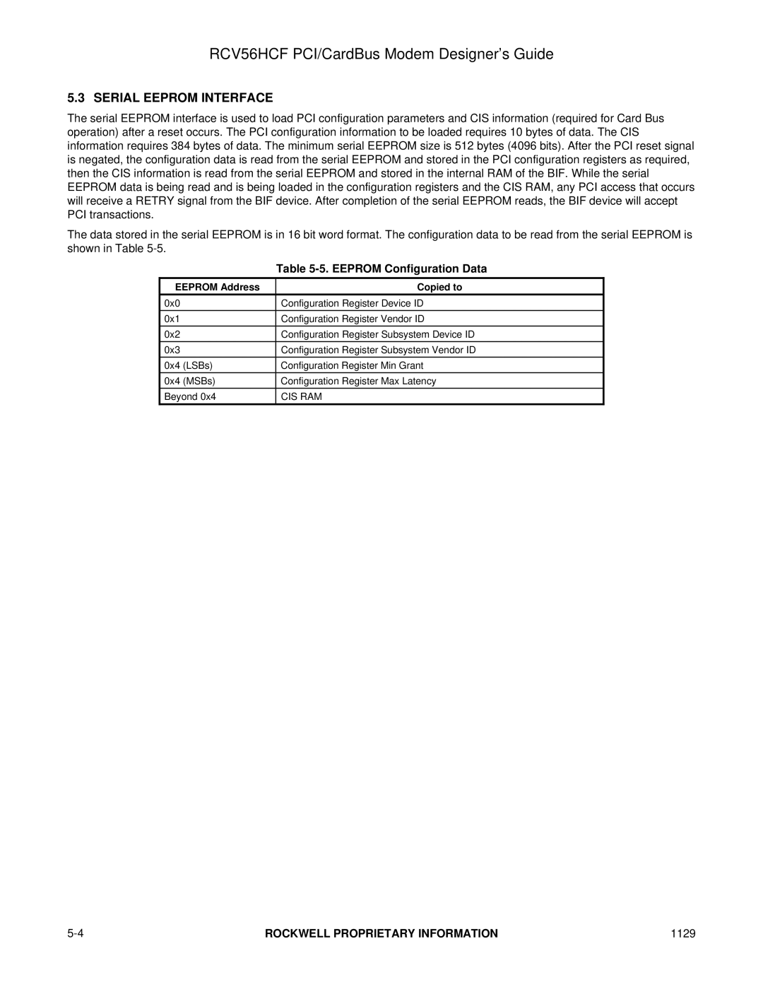
The data stored in the serial EEPROM is in 16 bit word format. The configuration data to be read from the serial EEPROM is shown in Table
|
| Table |
EEPROM Address | Copied to | |
0x0 |
| Configuration Register Device ID |
|
|
|
0x1 |
| Configuration Register Vendor ID |
0x2 |
| Configuration Register Subsystem Device ID |
0x3 |
| Configuration Register Subsystem Vendor ID |
|
|
|
0x4 | (LSBs) | Configuration Register Min Grant |
0x4 | (MSBs) | Configuration Register Max Latency |
Beyond 0x4 | CIS RAM | |
|
|
|
ROCKWELL PROPRIETARY INFORMATION | 1129 |