D. How to Use the Vent Graph

E. Venting Guidelines

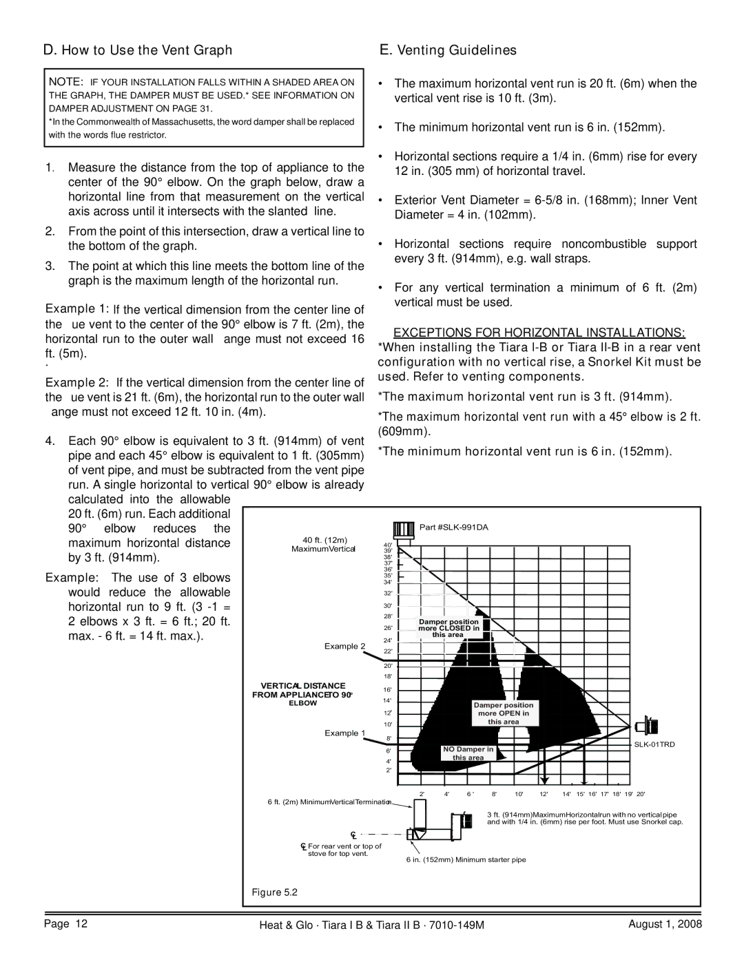
NOTE: IF YOUR INSTALLATION FALLS WITHIN A SHADED AREA ON THE GRAPH, THE DAMPER MUST BE USED.* SEE INFORMATION ON DAMPER ADJUSTMENT ON PAGE 31.

*In the Commonwealth of Massachusetts, the word damper shall be replaced with the words flue restrictor.

1. Measure the distance from the top of appliance to the center of the 90° elbow. On the graph below, draw a horizontal line from that measurement on the vertical axis across until it intersects with the slanted line.

The maximum horizontal vent run is 20 ft. (6m) when the vertical vent rise is 10 ft. (3m).

The minimum horizontal vent run is 6 in. (152mm).

Horizontal sections require a 1/4 in. (6mm) rise for every 12 in. (305 mm) of horizontal travel.

Exterior Vent Diameter = 6-5/8 in. (168mm); Inner Vent Diameter = 4 in. (102mm).

2.From the point of this intersection, draw a vertical line to

the bottom of the graph.


Horizontal sections require noncombustible support

3. The point at which this line meets the bottom line of the


every 3 ft. (914mm), e.g. wall straps.


graph is the maximum length of the horizontal run.

• For any

vertical

termination

a minimum of 6 ft. (2m)


Example 1: If the vertical dimension from the center line of


vertical must be used.


the flue vent to the center of the 90° elbow is 7 ft. (2m), the


EXCEPTIONS FOR HORIZONTAL INSTALLATIONS:

horizontal run to the outer wall flange must not exceed 16


*When installing the Tiara I-B or Tiara II-B in a rear vent

ft. (5m).


.


configuration with no vertical rise, a Snorkel Kit must be

Example 2: If the vertical dimension from the center line of

used. Refer to venting components.

the flue vent is 21 ft. (6m), the horizontal run to the outer wall

*The maximum horizontal vent run is 3 ft. (914mm).

flange must not exceed 12 ft. 10 in. (4m).

*The maximum horizontal vent run with a 45° elbow is 2 ft.


4. Each 90° elbow is equivalent to 3 ft. (914mm) of vent

(609mm).


pipe and each 45° elbow is equivalent to 1 ft. (305mm)

*The minimum horizontal vent run is 6 in. (152mm).

of vent pipe, and must be subtracted from the vent pipe


run. A single horizontal to vertical 90° elbow is already


calculated into

the

allowable


20 ft. (6m) run. Each additional


90°

elbow

reduces the


Part #SLK-991DA


maximum horizontal distance

40 ft. (12m)

40'


by 3 ft. (914mm).


MaximumVertical

39'


38'


37'


Example:

The use of 3 elbows


36'


35'


34'


would

reduce

the

allowable


32'


horizontal run to 9 ft. (3 -1 =


30'


28'


2 elbows x 3 ft. = 6 ft.; 20 ft.


Damper position


26'


max. - 6 ft. = 14 ft. max.).


more CLOSED in


24'


this area


Example 2


22'


20'


18'


VERTICAL DISTANCE

16'


FROM APPLIANCETO 90°


14'


ELBOW


Damper position


12'


more OPEN in


10'


this area


Example 1


8'


SLK-01TRD


6'


NO Damper in


4'


this area


2'


6 ft. (2m) MinimumVerticalTermination

2'


4' 6 '


8' 10' 12'

14' 15' 16' 17' 18' 19' 20'


3 ft. (914mm)MaximumHorizontalrun with no verticalpipe


C


and with 1/4 in. (6mm) rise per foot. Must use Snorkel cap.


L


CL For rear vent or top of


stove for top vent.


6 in. (152mm) Minimum starter pipe


Figure 5.2


Page 12

Heat & Glo · Tiara I B & Tiara II B · 7010-149M

August 1, 2008

Page 12
Image 12
Hearth and Home Technologies TIARAI-CES, TIARA II-B, TIARAI-BR-B, TIARA I-B, TIARAI-BK-B, TIARAI-CTO How to Use the Vent Graph

TIARAI-CTO, TIARAI-BK-B, TIARA II-B, TIARAI-BR-B, TIARAI-CES specifications

Hearth and Home Technologies offers a range of innovative gas and wood fireplace products, including the TIARA I-B, TIARA I-CTO, TIARA I-CES, TIARA II-B, and TIARA I-BR-B models. Each of these fireplaces combines aesthetic appeal with high functionality, creating a comfortable and stylish heating solution for any space.

The TIARA I-B is a versatile gas fireplace that features a contemporary design, perfect for modern homes. It comes with a large viewing area that showcases the beautiful flames while providing efficient heating. The model is equipped with advanced gas burner technology, ensuring a steady and even flame pattern, which enhances both the ambiance and warmth of the room.

The TIARA I-CTO boasts an innovative convection technology option, which allows for even heat distribution throughout the space. This model includes an easy-to-use remote control that enables users to adjust the flame height and heat output from across the room, providing an unparalleled level of convenience. Its sleek design can seamlessly blend into various interiors, making it a stylish choice for homeowners.

For those looking for a more efficient heating solution, the TIARA I-CES model incorporates a ceramic glass panel that enhances the fireplace's efficiency while maintaining an attractive aesthetic. The improved thermal performance allows for reduced fuel consumption and lower heating costs without compromising on warmth or style.

The TIARA II-B enhances the collection with its distinctive design and expanded features. This model comes with various decorative options, including multiple log set styles and media kits, allowing homeowners to customize their fireplace to match their unique taste. Its durable construction ensures longevity and reliability while providing warmth in colder months.

Finally, the TIARA I-BR-B is designed with a traditional aesthetic but incorporates modern technology. It delivers exceptional efficiency with the use of high-quality materials and advanced combustion technology. This fireplace not only provides a classic look but also meets modern energy efficiency standards, making it an eco-friendly choice for responsible heating.

In summary, the TIARA series from Hearth and Home Technologies combines beauty, technology, and efficiency. Each model is designed to suit different preferences and needs, ensuring that homeowners find the perfect fireplace solution. Whether you are after modern design or classic charm, the TIARA fireplaces deliver warmth and style in equal measure.