12 Electrical Information
A. Wiring Requirements
NOTICE: This appliance must be electrically wired and grounded in accordance with local codes or, in the absence of local codes, with National Electric Code ANSI/NFPA
Code CSA C22.1.
•Wire the appliance junction box to
•A
•Low voltage and 110 VAC voltage cannot be shared within the same wall box.
WARNING! Risk of Shock or Explosion! DO NOT wire 110V to the valve or to the appliance wall switch. Incorrect wiring will damage controls.
B. IntelliFire Plus™ Ignition System Wiring
•Wire the appliance junction box to 110 VAC for proper operation of the appliance.
WARNING! Risk of Shock or Explosion! DO NOT wire IPI controlled appliance junction box to a switched circuit. Incorrect wiring will override IPI safety lockout.
•Refer to Figure 12.2, IntelliFire PlusTM (IPI) Wiring Diagram.
•This appliance is equipped with an Intellifire control valve which operates on a 6 volt system.
C. Electrical Service and Repair
WARNING! Risk of Shock! Label all wires prior to dis- connection when servicing controls. Wiring errors can cause improper and dangerous operation. Verify proper operation after servicing.
WARNING! Risk of Shock! Replace damaged wire with type 105° C rated wire. Wire must have high temperature insulation.
D. Junction Box Installation
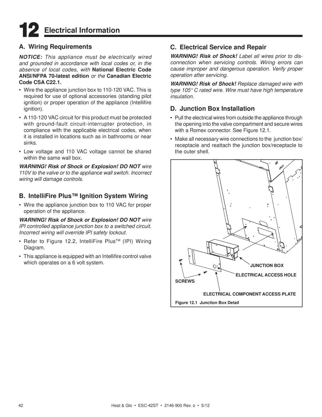
•Pull the electrical wires from outside the appliance through the opening into the valve compartment and secure wires with a Romex connector. See Figure 12.1.
•Make all necessary wire connections to the junction box/ receptacle and reattach the junction box/receptacle to the outer shell.
JUNCTION BOX |
ELECTRICAL ACCESS HOLE |
SCREWS |
ELECTRICAL COMPONENT ACCESS PLATE |
Figure 12.1 Junction Box Detail |
42 | Heat & Glo • |