CONNECTION
Terminal Positions
SD MEMORY
CARD
P![]()
INPUT(RGB)
PH35826
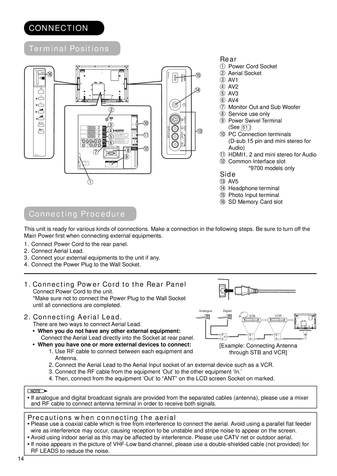
Rear
![]() Power Cord Socket
Power Cord Socket
Aerial Socket
![]() AV1
AV1
AV2
![]() AV3
AV3
AV4
![]() Monitor Out and Sub Woofer Service use only
Monitor Out and Sub Woofer Service use only
ANT
AUDIO
VIDEO |
Power Swivel Terminal
![]() OK
OK
PC
|
|
|
|
|
| ANALOG RGB |
|
|
|
| INPUT |
|
|
|
|
|
| (AV1) |
| INPUT(HDMI) |
|
|
|
| INPUT |
| AUDIO |
|
|
|
|
|
| |
|
|
|
| (AV2) |
|
|
|
|
|
|
| WOW, SRS and symbol are |
|
|
|
|
| INPUT | trademarks of SRS Labs, Inc. |
|
|
|
|
| (AV3) |
|
|
|
|
| AUDIO |
| Licensed by BBE Sound, Inc. under | HDMI2 |
Y/VIDEO | P | P | INPUT | one or more of the following US |
| |
|
|
|
| patents : 5510752, 5736897. |
| |
|
| L |
| (AV4) | BBE and BBE symbol are registered |
|
|
| C | R | trademarks of BBE Sound, Inc. |
| |
| SUB WOOFER |
| AUDIO | OUTPUT |
|
|
|
|
|
|
| HDMI1 | |
|
| L | R |
| SERVICE USE ONLY |
|
|
|
|
|
|
| COMMON |
|
|
|
|
|
| INTERFACE |
PH35814 |
|
|
|
|
|
|
|
|
|
|
| POWER SWIVEL |
|
| A C |
|
|
|
|
|
|
|
|
|
|
| C.2C.1 |
Connecting Procedure
|
| S- |
INPUT(AV5) | L/MONO | AUDIO VIDEO |
| R |
|
(See 51 )
![]() PC Connection terminals
PC Connection terminals
![]() HDMI1, 2 and mini stereo for Audio
HDMI1, 2 and mini stereo for Audio
Common Interface slot *9700 models only
Side
![]() AV5
AV5
Headphone terminal
![]() Photo Input terminal
Photo Input terminal
SD Memory Card slot
This unit is ready for various kinds of connections. Make a connection in the following steps. Be sure to turn off the Main Power first when connecting external equipments.
1.Connect Power Cord to the rear panel.
2.Connect Aerial Lead.
3.Connect your external equipments to the unit if any.
4.Connect the Power Plug to the Wall Socket.
1. Connecting Power Cord to the Rear Panel
Connect Power Cord to the unit.
*Make sure not to connect the Power Plug to the Wall Socket until all connections are completed.
2. Connecting Aerial Lead.
Analogue
Digital
![]()
![]() STB VCR
STB VCR
There are two ways to connect Aerial Lead.
![]() When you do not have any other external equipment:
When you do not have any other external equipment:
Connect the Aerial Lead directly into the Socket at rear panel.
IN | IN |
OUT | OUT |
![]() When you have one or more external devices to connect: 1. Use RF cable to connect between each equipment and
When you have one or more external devices to connect: 1. Use RF cable to connect between each equipment and
Antenna.
2.Connect the Aerial Lead to the Aerial Input socket of an external device such as a VCR.
3.Connect the RF cable from the equipment ‘Out’ to the other equipment ‘In.’
4.Then, connect from the equipment ‘Out’ to “ANT” on the LCD screen Socket on marked.
NOTE
![]() If analogue and digital broadcast signals are provided from the separated cables (antenna), please use a mixer and RF cable to connect antenna terminal in order to receive both signals.
If analogue and digital broadcast signals are provided from the separated cables (antenna), please use a mixer and RF cable to connect antenna terminal in order to receive both signals.
14
Precautions when connecting the aerial
![]() Please use a coaxial cable which is free from interference to connect the aerial. Avoid using a parallel flat feeder wire as interference may occur, causing reception to be unstable and stripe noise to appear on the screen.
Please use a coaxial cable which is free from interference to connect the aerial. Avoid using a parallel flat feeder wire as interference may occur, causing reception to be unstable and stripe noise to appear on the screen.
![]() Avoid using indoor aerial as this may be affected by interference. Please use CATV net or outdoor aerial.
Avoid using indoor aerial as this may be affected by interference. Please use CATV net or outdoor aerial.
![]() If noise appears in the picture of
If noise appears in the picture of