PDX Series
PDX SERVICE PROCEDURE V
Blower Temperature Switch Testing
and Replacement
Blower Temperature Switch
Replacement.
![]()
![]() WARNING
WARNING
120 volt potential exposure. Use caution
to avoid personal injury.
Step 1. Position gas control power switch to the “OFF” position and unplug heater from wall outlet.
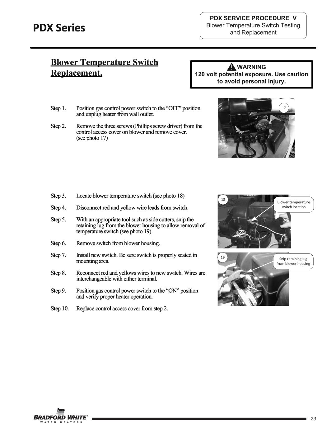
Step 2. Remove the three screws (Phillips screw driver) from the control access cover on blower and remove cover.
(see photo 17)
Step 3. Locate blower temperature switch (see photo 18)
Step 4. Disconnect red and yellow wire leads from switch.
Step 5. With an appropriate tool such as side cutters, snip the retaining lug from the blower housing to allow removal of temperature switch (see photo 19).
Step 6. Remove switch from blower housing.
18
17
Blower temperature
switch location
Step 7. Install new switch. Be sure switch is properly seated in mounting area.
Step 8. Reconnect red and yellows wires to new switch. Wires are interchangeable with either terminal.
Step 9. Position gas control power switch to the “ON” position and verify proper heater operation.
Step 10. Replace control access cover from step 2.
19 | Snip retaining lug |
| |
| from blower housing |
Page 23
23