PDX Series
PDX SERVICE PROCEDURE II
Pilot testing, Cleaning and Replacement
Pilot Inspection, Testing and Replacement
Step 1. Position gas control power switch to the “OFF” position and unplug heater from wall outlet.
Step 2. Turn off gas supply to water heater.
Step 3. Remove outer jacket door and remove inner door per service proceedure XIII on page 35.
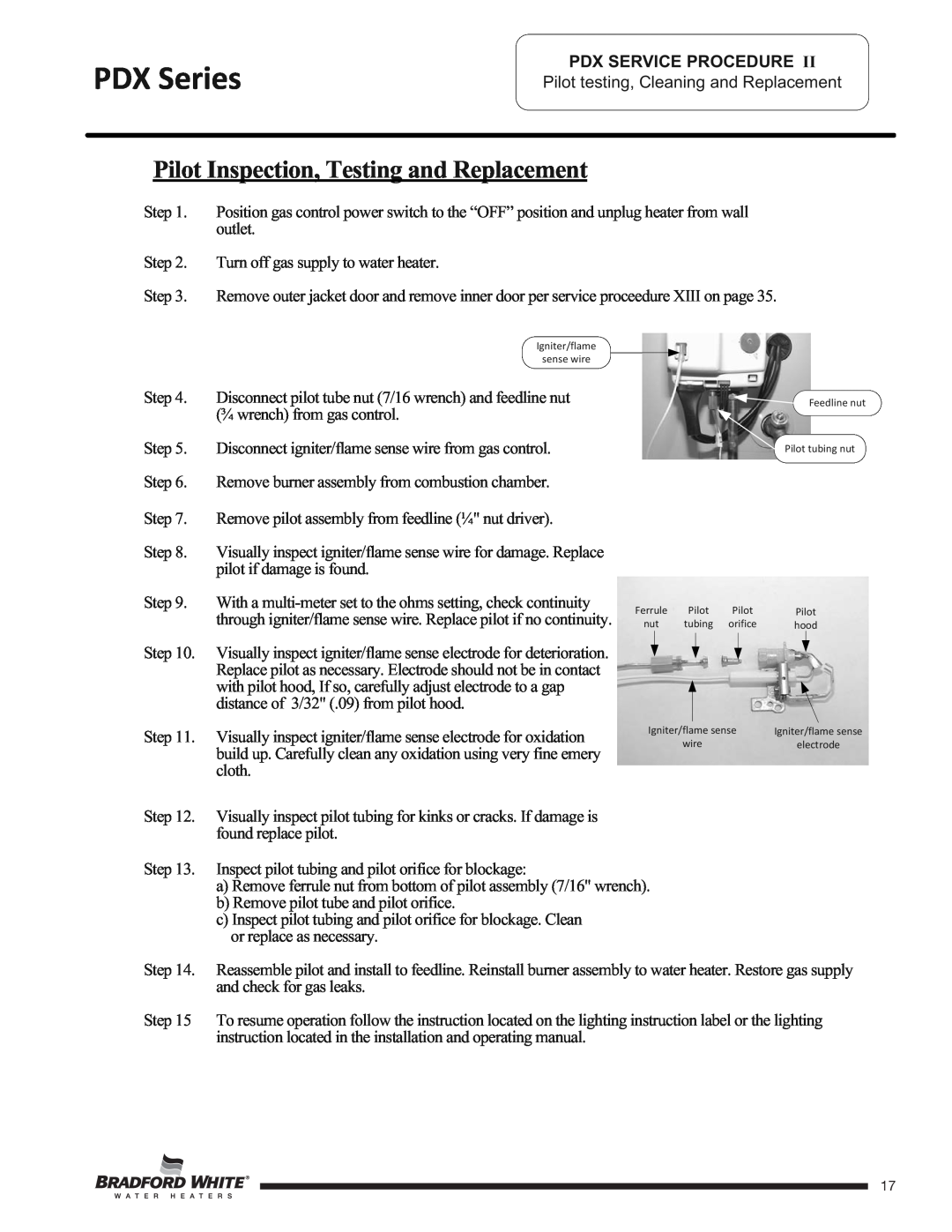
Igniter/flame
sense wire
Step 4. Disconnect pilot tube nut (7/16 wrench) and feedline nut (¾ wrench) from gas control.
Step 5. Disconnect igniter/flame sense wire from gas control.
Step 6. Remove burner assembly from combustion chamber.
Step 7. Remove pilot assembly from feedline (¼" nut driver).
Step 8. Visually inspect igniter/flame sense wire for damage. Replace pilot if damage is found.
Step 9. With a
Ferrule | Pilot | Pilot |
nut | tubing | orifice |
Feedline nut
Pilot tubing nut
Pilot
hood
Step 10. | Visually inspect igniter/flame sense electrode for deterioration. |
|
|
|
|
|
|
|
| ||
| Replace pilot as necessary. Electrode should not be in contact |
|
|
|
|
| with pilot hood, If so, carefully adjust electrode to a gap |
|
|
|
|
| distance of 3/32" (.09) from pilot hood. |
|
|
|
|
|
|
|
|
|
|
Step 11. | Visually inspect igniter/flame sense electrode for oxidation | Igniter/flame sense | |||
| wire | ||||
| build up. Carefully clean any oxidation using very fine emery |
|
|
|
|
| cloth. |
|
|
|
|
Step 12. | Visually inspect pilot tubing for kinks or cracks. If damage is |
|
|
|
|
| found replace pilot. |
|
|
|
|
Step 13. | Inspect pilot tubing and pilot orifice for blockage: |
|
|
|
|
a) Remove ferrule nut from bottom of pilot assembly (7/16" wrench). b) Remove pilot tube and pilot orifice.
c) Inspect pilot tubing and pilot orifice for blockage. Clean or replace as necessary.
Igniter/flame sense
electrode
Step 14. Reassemble pilot and install to feedline. Reinstall burner assembly to water heater. Restore gas supply and check for gas leaks.
Step 15 To resume operation follow the instruction located on the lighting instruction label or the lighting instruction located in the installation and operating manual.
Page 17
17