PDX Series
PDX SERVICE PROCEDURE IX
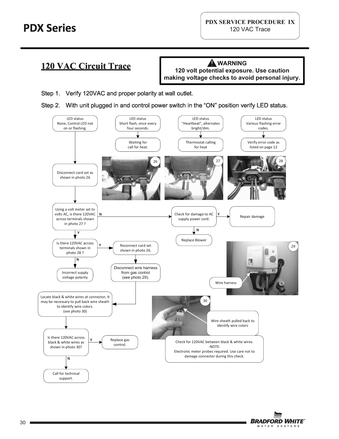
120 VAC Trace
120 VAC Circuit Trace
![]()
![]() WARNING
WARNING
120 volt potential exposure. Use caution
making voltage checks to avoid personal injury.
Step 1. Verify 120VAC and proper polarity at wall outlet.
Step 2. With unit plugged in and control power switch in the “ON” position verify LED status.
LED status | LED status | |||
None, Control LED not | Short flash, once every | |||
on or flashing. | four seconds. | |||
|
|
| ||
|
|
|
| |
|
| Waiting for | ||
|
| call for heat. | ||
|
| 26 | ||
Disconnect cord set as | ||||
|
| |||
shown in photo 26 |
|
| ||
Using a volt meter set to volts AC, is there 120VAC N across terminals shown
in photo 27 ?
| Y |
|
|
|
|
|
Is there 120VAC across | Y |
| Reconnect cord set | |||
terminals shown in |
| |||||
|
|
| shown in photo 26. | |||
photo 28 ? |
|
|
| |||
|
|
|
|
| ||
| N |
|
|
|
|
|
|
|
|
|
|
| |
|
| Disconnect wire harness | ||||
|
|
|
| |||
|
|
|
| |||
Incorrect supply |
|
|
| from gas control | ||
voltage polarity |
|
|
| (see photo 29). | ||
Locate black & white wires at connector, It |
|
|
| |||
|
|
| ||||
may be necessary to pull back wire sheath |
|
|
| |||
to identify wire colors. |
|
|
|
|
| |
(see photo 30) |
|
|
|
|
| |
Is there 120VAC across | Y | Replace gas | ||
black & white wires as | ||||
| control. | |||
shown in photo 30? |
| |||
|
| |||
| N |
|
| |
|
|
| ||
|
|
|
| |
Call for technical |
|
| ||
support. |
|
| ||
LED status | LED status | ||
“Heartbeat”, alternates | Various flashing error | ||
bright/dim. | codes. | ||
|
|
| |
|
|
|
|
Thermostat calling | Verify error code as | ||
for heat | listed on page 12 | ||
27 | 28 | ||
Check for damage to AC Y | Repair damage | |||
supply power cord. |
| |||
| ||||
| N |
| ||
|
| |||
Replace Blower |
| |||
29
Wire harness
30
Wire sheath pulled back to
identify wire colors
Check for 120VAC between black & white wires.
Electronic meter probes required. Use care not to
damage connector during this check.
Page 30
30