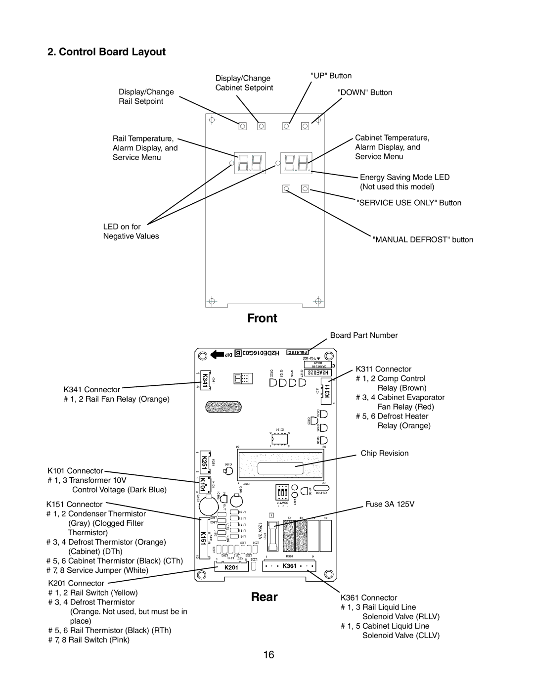
2. Control Board Layout
Display/Change
Rail Setpoint
Rail Temperature,
Alarm Display, and
Service Menu
LED on for
Negative Values
Display/Change Cabinet Setpoint
"UP" Button
"DOWN" Button
Cabinet Temperature,
Alarm Display, and
Service Menu
![]() Energy Saving Mode LED
Energy Saving Mode LED
(Not used this model) "SERVICE USE ONLY" Button
"MANUAL DEFROST" button
K341 Connector ![]()
# 1, 2 Rail Fan Relay (Orange)
K101 Connector
# 1, 3 Transformer 10V
Control Voltage (Dark Blue)
K151 Connector
#1, 2 Condenser Thermistor (Gray) (Clogged Filter Thermistor)
#3, 4 Defrost Thermistor (Orange) (Cabinet) (DTh)
#5, 6 Cabinet Thermistor (Black) (CTh)
#7, 8 Service Jumper (White)
K201 Connector
#1, 2 Rail Switch (Yellow)
#3, 4 Defrost Thermistor
(Orange. Not used, but must be in place)
#5, 6 Rail Thermistor (Black) (RTh)
#7, 8 Rail Switch (Pink)
Front
Rear
Board Part Number
K311 Connector
#1, 2 Comp Control Relay (Brown)
#3, 4 Cabinet Evaporator Fan Relay (Red)
#5, 6 Defrost Heater Relay (Orange)
Chip Revision
Fuse 3A 125V
K361 Connector
#1, 3 Rail Liquid Line Solenoid Valve (RLLV)
#1, 5 Cabinet Liquid Line Solenoid Valve (CLLV)
16