3)Allow the vacuum pump to pull down to a 29.9" Hg vacuum. Evacuating period depends on pump capacity.
4)Close both gauge manifold valves.
5)Turn off the vacuum pump. Disconnect the vacuum pump hose and attach it to a refrigerant service cylinder. Remember to loosen the connection, and purge the air from the hose. See the nameplate for the required refrigerant charge. Hoshizaki recommends only virgin refrigerant or reclaimed refrigerant which meets ARI Standard No. 700 (latest edition) be used.
6)A liquid charge is recommended for charging an
7)Open the
8)If necessary, add any remaining charge to the system through the compressor access valve. Use a throttling valve or liquid dispensing device to add the remaining liquid charge through the compressor access valve with the unit running.
9)Back out the receiver service valve stem all the way and tighten. Disconnect the gauge manifold hoses.
Note: Be sure the receiver service valve stem is backseated all the way out and tight before disconnecting the gauge manifold hose.
10)Cap the valves to prevent possible leaks.
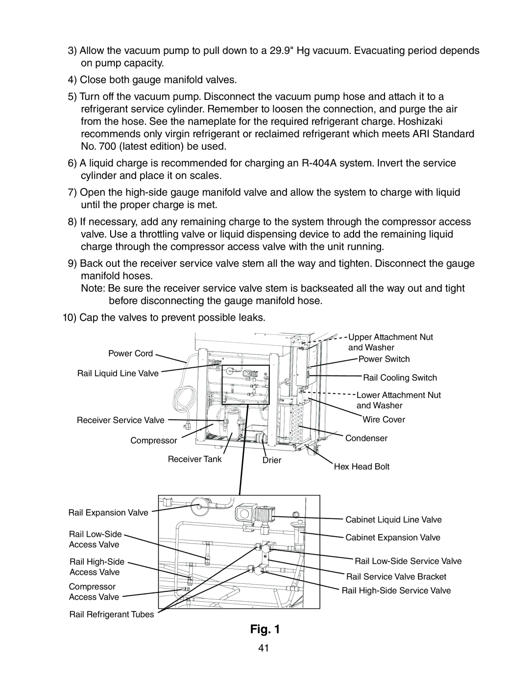
Power Cord
Rail Liquid Line Valve |
Receiver Service Valve |
Upper Attachment Nut
and Washer
Power Switch
![]()
![]()
![]()
![]()
![]() Rail Cooling Switch
Rail Cooling Switch
![]()
![]()
![]()
![]()
![]()
![]()
![]()
![]()
![]()
![]()
![]()
![]()
![]() Lower Attachment Nut
Lower Attachment Nut
and Washer
Wire Cover
Compressor |
| Condenser |
Receiver Tank | Drier | Hex Head Bolt |
|
|
Rail Expansion Valve | Cabinet Liquid Line Valve | |
| ||
Rail | Cabinet Expansion Valve | |
Access Valve | ||
| ||
Rail | Rail | |
Access Valve | Rail Service Valve Bracket | |
Compressor | ||
Rail | ||
Access Valve | ||
| ||
Rail Refrigerant Tubes |
|
Fig. 1
41