a.Turn on or restart the device, and then press esc while the “Press the ESC key for Startup Menu” message is displayed at the bottom of the screen.
b.Press f10 to enter Computer Setup.
![]() NOTE: If the BIOS is protected with an Administrator password, enter the password.
NOTE: If the BIOS is protected with an Administrator password, enter the password.
2.Select Advanced, and then select HP Touchpoint Manager Options.
3.Clear the Allow Activation check box.
4.Select Save changes and exit.
Back cover
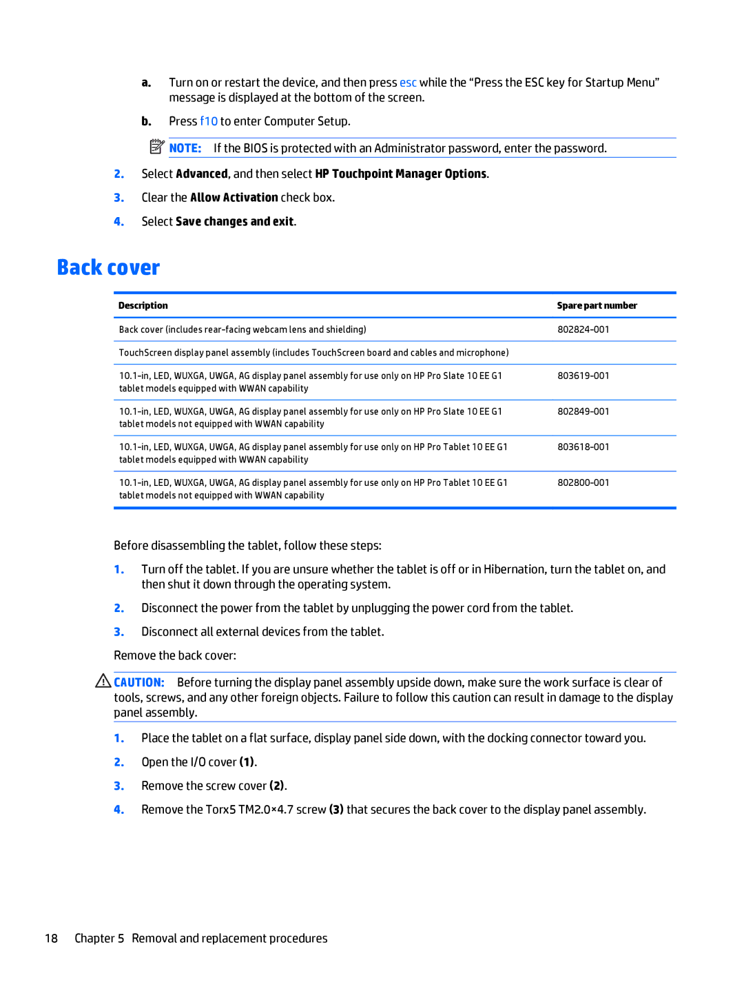
Description | Spare part number |
|
|
Back cover (includes | |
|
|
TouchScreen display panel assembly (includes TouchScreen board and cables and microphone) |
|
|
|
tablet models equipped with WWAN capability |
|
|
|
tablet models not equipped with WWAN capability |
|
|
|
tablet models equipped with WWAN capability |
|
|
|
tablet models not equipped with WWAN capability |
|
|
|
Before disassembling the tablet, follow these steps:
1.Turn off the tablet. If you are unsure whether the tablet is off or in Hibernation, turn the tablet on, and then shut it down through the operating system.
2.Disconnect the power from the tablet by unplugging the power cord from the tablet.
3.Disconnect all external devices from the tablet.
Remove the back cover:
![]() CAUTION: Before turning the display panel assembly upside down, make sure the work surface is clear of tools, screws, and any other foreign objects. Failure to follow this caution can result in damage to the display panel assembly.
CAUTION: Before turning the display panel assembly upside down, make sure the work surface is clear of tools, screws, and any other foreign objects. Failure to follow this caution can result in damage to the display panel assembly.
1.Place the tablet on a flat surface, display panel side down, with the docking connector toward you.
2.Open the I/O cover (1).
3.Remove the screw cover (2).
4.Remove the Torx5 TM2.0×4.7 screw (3) that secures the back cover to the display panel assembly.
18 Chapter 5 Removal and replacement procedures
