Chapter 2, Making Measurements
Average Power
Steps | 1 | Connect the equipment as shown in figure 6. |
| 2 | In the main menu, enter the Base Station Channel number for the transmitter |
|
| being tested. |
| 3 | Set up the base station to transmit on the channel number entered in step 2. |
| 4 | From the main menu, choose Perform Average Power Measurements. |
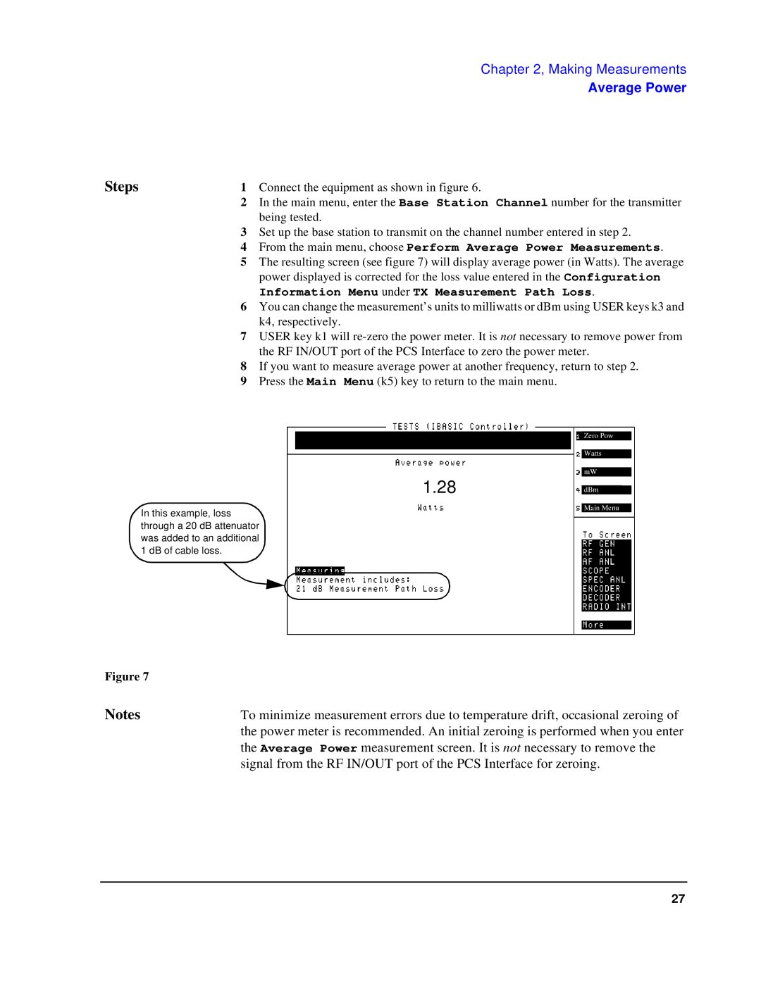
| 5 | The resulting screen (see figure 7) will display average power (in Watts). The average |
|
| power displayed is corrected for the loss value entered in the Configuration |
|
| Information Menu under TX Measurement Path Loss. |
| 6 | You can change the measurement’s units to milliwatts or dBm using USER keys k3 and |
|
| k4, respectively. |
| 7 | USER key k1 will |
|
| the RF IN/OUT port of the PCS Interface to zero the power meter. |
| 8 | If you want to measure average power at another frequency, return to step 2. |
| 9 | Press the Main Menu (k5) key to return to the main menu. |
1.28
In this example, loss through a 20 dB attenuator was added to an additional 1 dB of cable loss.
Zero Pow
Watts
mW
dBm
Main Menu
Figure 7 |
|
Notes | To minimize measurement errors due to temperature drift, occasional zeroing of |
| the power meter is recommended. An initial zeroing is performed when you enter |
| the Average Power measurement screen. It is not necessary to remove the |
| signal from the RF IN/OUT port of the PCS Interface for zeroing. |
27