Hp Portable Chillers
Shipping Information
Table of Contents
Operation
HP Portable Chillers
Safety
How to Use This Manual
Safety Symbols Used in this Manual
Wear Safety Glasses and Work Gloves
Responsibility
Functional Description
Models Covered in This Manual
General Description
Chilled Water Circuit
Refrigeration Circuit
Standard Features
Mechanical Features
Other Mechanical Features
Electrical Features
Refrigeration Features
Controller Features
Other Features
Safety Devices and Interlocks
High/Low Thermostat Control
Crankcase Heater
High Pressure Cutout
Oil Pressure Safety Switch
Fan Cycling Switch
Pressure Switch
Flow Switch
Optional Features
Mounting Features
Optional Pump Amperages Voltage Construction Full Load Amps
Installation
Uncrating
Electrical Connections
Process Water Connections
Bypass Valve Considerations
Galvanic Corrosion Considerations
Water Treatment Considerations
Condenser Considerations
Water-Cooled Chiller Condensers
Air-Cooled Chiller Condensers
Remote Air-Cooled Chiller Condensers
Page
Equivalent Length in Feet for Valves and Fittings
Chiller Condenser Charge Field Installed Piping Charge
Refrigerant Charge Determination
Three-Phase Compressors
Checking Motor Direction
Water Pumps
Condenser Fan
Water Reservoir
Part Number Description
Ethylene Glycol and Propylene Glycol Curves
Automatic Water Make-Up Option
Initial Start-Up
Panel Buttons, Indicator Lights, and Switches
E5CK Controller Indicator Name Description
Operation
Microprocessor Controllers
Indicator Name Description
Sterlco 2000 Controller Indicator Name Description
2000
See on Indicator Name Description
Graphic Panel
Indicator Name Description
Typical Graphic Panels With E5CK Controller
With Sterlco 2000 Controller
Setting the Process Water Temperatures
Auto-Tuning
Start-up
Optional Communications
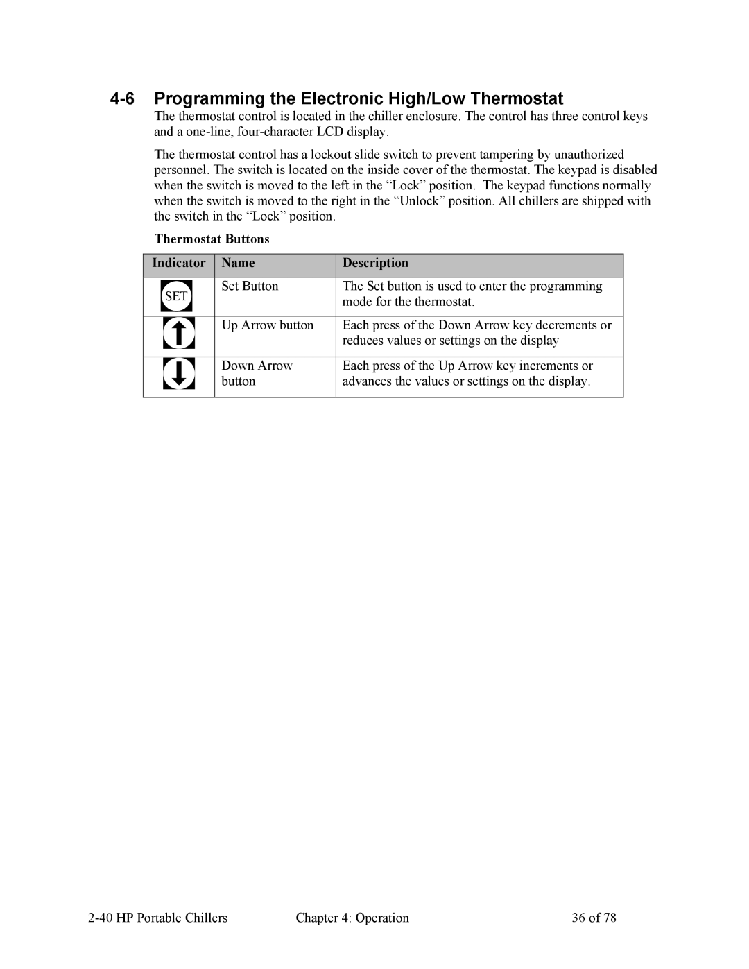
Thermostat Buttons Indicator Name Description
Programming the Electronic High/Low Thermostat
Stage 2 High Temperature Protection
Select Fahrenheit or Celsius
Stage 1 Freeze Protection
Maintenance
Filter Cleaning
Lubrication
Maintaining the Condenser
Maintaining the Evaporator
Evaporator Process Piping Y-Strainer
Air- and Remote Air-Cooled Chillers
Preventative Maintenance Service
Troubleshooting
HP Portable Chillers Troubleshooting
HP Portable Chillers Troubleshooting
Warranty
Appendix
Service Department
Technical Assistance
Parts Department
Sales Department
Drawings and Specifications
Hp and 3 1/2 hp Air-Cooled Portable Chillers
Hp and 7.5 hp Air-Cooled Portable Chillers
Hp and 15 hp Air-Cooled Portable Chillers
20 hp, 25 hp, and 30 hp Air-Cooled Portable Chillers
Hp and 3.5 hp Water-Cooled Portable Chillers
Nominal Condenser water Nominal cooling Water Com
In. NPT Height Width Depth Lbs
Hp and 7.5 hp Water-Cooled Portable Chillers
Hp and 15 hp Water-Cooled Portable Chillers
20 hp, 25 hp, and 30 hp Water-Cooled Portable Chillers
Hp and 40 hp Water-Cooled Portable Chillers
Nominal cooling Com Refrigeration Power in amps e
Hp and 7.5 hp Remote Air-Cooled Portable Chillers
12.8 17.3
748
Hp and 15 hp Remote Air-Cooled Portable Chillers
Nominal cooling Com Refrigeration
Pres Nom Connections
15.0 40.9 34.0 74.7
Hp through 40 hp Remote Air-Cooled Portable Chillers
To/from No tank Tank, to/from Height Width Depth Lbs
Remote Condenser Assembly Models
‘A’in ‘B’in ‘C’in ‘D’in ODSin
Pump Curves, Flow, and Pressure Considerations
Hertz Pump Curves
DWG. No. S0554823
Water Pressure Drop Tables
Calculating Chiller Nominal Flow and Pressure to Process
Recirculation Pump Specifications
Recirc. power Flow Rate ∆ pressure Gpm Lpm Psi KPa
Flow and Pressure Considerations
Remote Air-Cooled Chiller Configurations
Configuration a
Configuration B Configuration C
Typical Ductwork for Air-Cooled Chillers
Piping Diagrams
Central and Gravity Return Piping with Standpipe Diagram
Typical Piping Schematic, 2 and 3 1/2 hp Models
HP Portable Chillers Appendix
HP Portable Chillers Appendix
Typical Piping Schematic, 5 hp through 40 hp, No-Pump Models
HP Portable Chillers Appendix
Electrical Schematics
Time-delay Relays Disconnect Switch Optional
Typical Electrical Subpanel
Speed Fuses
Typical Electrical Schematic, 2 hp and 3 1/2 hp Models
Typical Power Wiring Schematic, 5 hp through 40 hp Models
A0554815
HP Portable Chillers Appendix
DWG A0554931
DWG A0562343
DWG A0562435
Typical Wiring Schematic, 35 hp and 40 hp Models with Pump
DWG A0562434

