Manuals
/
HP
/
Computer Equipment
/
Laptop
HP
DV1000 nx4800
manual
Miscellaneous Plastics Kit
Models:
DV1000 nx4800
DV1000
1
86
235
235
Download
235 pages
36.39 Kb
83
84
85
86
87
88
89
90
Troubleshooting
Flowchart Description
Pin Signal
Dimension
Maintenance
Resetting the Notebook
Access time
Display Assembly
Battery packs
Temperature
Page 86
Image 86
Illustrated Parts Catalog
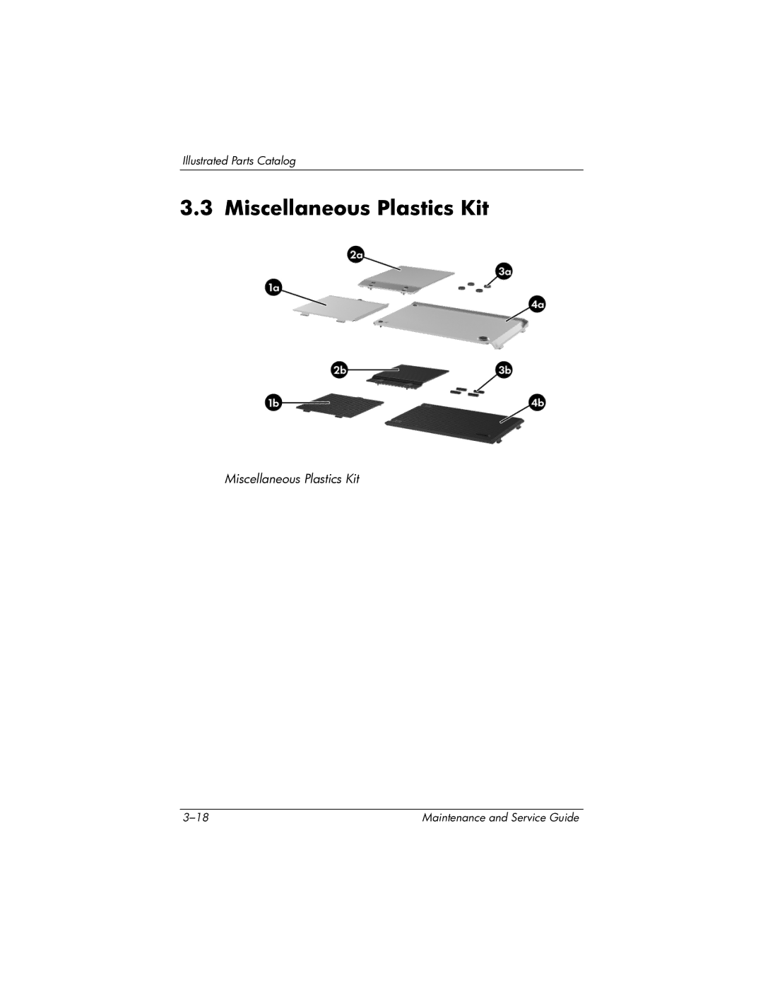
3.3 Miscellaneous Plastics Kit
Miscellaneous Plastics Kit
3–18
Maintenance and Service Guide
Page 85
Page 87
Page 86
Image 86
Page 85
Page 87
Contents
Maintenance and Service Guide
Page
Contents
Removal and Replacement Procedures
Product Description
Features
Product Description
Resetting the Notebook
Power Management
External Components
HP Pavilion dv1000
Speakers Produces stereo sound
Front Components, HP Compaq nx4800 Compaq Presario
Front Components HP Compaq nx4800 and Compaq Presario
Right-Side Components, HP Pavilion dv1000
Right-Side Components HP Pavilion dv1000
Right-Side Components, HP Compaq nx4800 Compaq Presario
Right-Side Components HP Compaq nx4800 and Compaq Presario
Rear and Left-Side Components, HP Pavilion dv1000
Rear and Left-Side Components HP Pavilion dv1000
Product Description
Component Function
Keyboard Components, HP Pavilion dv1000
Keyboard Components
Keyboard Components, HP Compaq nx4800 Compaq Presario
Keyboard Components HP Compaq nx4800 and Compaq Presario
Top Components, Part
Top Components, Part HP Pavilion dv1000
Top Components, Part 2, HP Pavilion dv1000
Top Components, Part HP Pavilion dv1000
Top Components, Part 3, HP Pavilion dv1000
Top Components, Part
Top Components, Part HP Compaq nx4800 and Compaq Presario
Top Components, Part HP Compaq nx4800 and Compaq Presario
Top Components, Part 2, HP Compaq nx4800 Compaq Presario
Top Components, Part HP Compaq nx4800 and Compaq Presario
Bottom Components HP Pavilion dv1000
Other applicable regulatory labels
Bottom Components HP Compaq nx4800 and Compaq Presario
Bottom Components HP Compaq nx4800 and Compaq Presario
Design Overview
Troubleshooting
Computer Setup
Main Menu
Select To Do This
Selecting from the Security Menu
Security Menu
Selecting from the Advanced Menu
Advanced Menu
Flowchart Description
Troubleshooting Flowcharts
Troubleshooting Flowcharts Overview
Troubleshooting Flowcharts Overview
Flowchart 2.1-Initial Troubleshooting
Flowchart No Power Part
Flowchart 2.2-No Power, Part
Flowchart 2.3-No Power, Part
Flowchart 2.4-No Power, Part
External
Flowchart 2.5-No Power, Part
Flowchart 2.6-No Video, Part
Flowchart 2.7-No Video, Part
Flowchart No Video Part
Flowchart 2.8-Nonfunctioning Expansion Base if applicable
Nonfunctioning expansion base
Flowchart 2.9-No Operating System OS Loading
Go to Flowchart 2.13-No OS Loading Diskette Drive
Flowchart 2.10-No OS Loading, Hard Drive, Part
Loading
Flowchart 2.11-No OS Loading, Hard Drive, Part
Flowchart No OS Loading Hard Drive, Part
Flowchart 2.12-No OS Loading, Hard Drive, Part
Can bad sectors be fixed?
Flowchart 2.13-No OS Loading, Diskette Drive
Utility?
Flowchart 2.14-No OS Loading, CD-ROM or DVD-ROM Drive
Flowchart 2.15-No OS Loading for QuickPlay Application, Part
Flowchart 2.16-No OS Loading for QuickPlay Application, Part
Flowchart 2.17-No Audio, Part
Flowchart 2.18-No Audio, Part
Flowchart 2.19-Nonfunctioning Device
Cmos
Flowchart 2.20-Nonfunctioning Keyboard
Flowchart 2.21-Nonfunctioning Pointing Device
Pointing device Not operating Properly Connect notebook
Flowchart 2.22-No Network/Modem Connection
Illustrated Parts Catalog
Serial Number Location
Illustrated Parts Catalog
Spare Part
Wireless antenna cables not illustrated
Spare Parts Notebook Major Components
Left and right display hinge covers and brackets
Illustrated Parts Catalog
Spare Part
Illustrated Parts Catalog
Keyboards
Illustrated Parts Catalog
367762-001
Illustrated Parts Catalog
Speaker assemblies
10 USB/S-Video controller boards
Menu control button board includes bracket
Illustrated Parts Catalog
Optical drives include bezel
Battery packs
Base enclosures
Illustrated Parts Catalog
Mini PCI communications cards
5400-rpm
4200-rpm
Memory modules 266 MHz
Illustrated Parts Catalog
Miscellaneous Plastics Kit
Miscellaneous Plastics Kit
Miscellaneous Plastics Kit Spare Part Number Information
Mass Storage Devices
Mass Storage Devices Spare Part Number Information
Spare Part
Miscellaneous
Spare Parts Miscellaneous not illustrated
Description Number Power cords
Spare Part Number Description
Sequential Part Number Listing
Spare Parts Sequential Part Number Listing
China, and the United States
Spare Parts Sequential Part Number Listing
Spare Parts Sequential Part Number Listing
Spare Parts Sequential Part Number Listing
Spare Parts Sequential Part Number Listing
Spare Parts Sequential Part Number Listing
Power cord for use in Australia, Hong Kong, New Zealand,
Spare Parts Sequential Part Number Listing
Service Considerations
Tools Required
Preventing Damage to Removable Drives
Plastic Parts
Preventing Electrostatic Damage
Packaging and Transporting Precautions
Workstatinon Precautions
Use the following grounding precautions at workstations
Grounding Equipment and Methods
Removal and Replacement Preliminaries
Relative Humidity Event 10% 40% 55%
Typical Electrostatic Voltage Levels
Static-Shielding Materials
Material Use Voltage Protection Level
Removal and Replacement Procedures
Serial Number
# of Screws Removed
Disassembly Sequence Chart
Disassembly Sequence Chart
Disassembly Sequence Chart
Preparing the Notebook for Disassembly
Reverse the above procedure to install the battery pack
Removing the Hard Drive Cover
Spare Part Number Information
Removing the Hard Drive Frame and Connector
Replacing the Notebook Feet
Memory Module
Removing the Memory Module Compartment Cover
Reverse the above procedure to install a memory module
Mini PCI Communications Card
Removing the Mini PCI Compartment Cover
Removing a Mini PCI Communications Card
Optical Drive
Reverse the above procedure to install an optical drive
Switch Cover
Removal and Replacement Procedures
Removal and Replacement Procedures
Swing the rear edge of the switch cover forward
Removal and Replacement Procedures
Reverse the above procedure to install the switch cover
Keyboard
Removal and Replacement Procedures
Removal and Replacement Procedures
Remove the keyboard
Removal and Replacement Procedures
Removal and Replacement Procedures
Display Assembly
Disconnecting the Wireless Antenna Cables
Removal and Replacement Procedures
Removal and Replacement Procedures
Reverse the above procedure to install the display assembly
Base Enclosure
Removal and Replacement Procedures
Removal and Replacement Procedures
Removal and Replacement Procedures
Reverse the above procedure to install the base enclosure
12 USB/S-Video Controller Board
Removing the USB/S-Video Controller Board
Speaker Assembly
Reverse the above procedure to install the speaker assembly
RTC Battery
Menu Control Button Board
Disconnecting the Menu Control Button Board Cable
Removing the Menu Control Button Board and Shield
Heat Sink
Reverse the above procedure to install the heat sink
17 Fan
Reverse the above procedure to install the fan
Processor
Reverse the above procedure to install a processor
System Board
Disconnecting the TouchPad Cable
Removal and Replacement Procedures
Removal and Replacement Procedures
Releasing the System Board, Part
Releasing the System Board, Part
Reverse the above procedure to install the system board
LED Board
Removal and Replacement Procedures
Removal and Replacement Procedures
Dimensions
Stand-alone power requirements
Maximum altitude unpressurized
Temperature
Relative humidity noncondensing
Shock
Inch, WXGA, SVA Display
Hard Drives
Primary 6-cell, Li-Ion Battery Pack
Energy
Center hole diameter
24X DVD/CD-RW Combo Drive
Applicable disk Read Write
Disk diameter
Track pitch
Access time
Disk thickness
Audio output level
4X DVD+RW/R and CD-RW Combo Drive
DVD-RW
4X DVD±RW/R and CD-RW Combo Drive
DVD
8X DVD±RW/R and CD-RW Combo Drive
8X DVD±RW/R and CD-RW Combo Drive
8X Max DVD-ROM Drive
Applicable disk
Cache buffer
System DMA
Hardware DMA System Function
System Interrupts
Hardware IRQ System Function
IRQ12
System I/O Addresses
Address hex
16F Unused
VGA
System Memory Map
Size Memory Address System Function
Pin Signal
Table A-1 Universal Serial Bus
Table A-2 RJ-45 Network
Table A-3 Video-Out
Table A-4 External Monitor
Table A-5 RJ-11 Modem
Table A-6 Audio-In Microphone
Table A-7 Audio-Out Headphone
Power Cord Set Requirements
Conductor Power Cord Set
General Requirements
Country Accredited Agency Applicable Note Number
Conductor Power Cord Set Requirements
Country-Specific Requirements
BSI
Screw Listing
Head
Color Qty Length Thread Width Black Where used
Table C-1 Phillips PM2.0×5.0 Screw
Table C-1 Phillips PM2.0×5.0 Screw
Table C-1 Phillips PM2.0×5.0 Screw
Color Qty Length Thread Width Silver Where used
Table C-2 Phillips PM2.5×4.0 Screw
Table C-3 Phillips PM2.0×7.0 Screw
Phillips M2.0×6.0 Screw Locations
Table C-3 Phillips PM2.0×6.0 Screw
Table C-3 Phillips PM2.0×6.0 Screw
Table C-4 Phillips PM2.0×4.0 Screw
Table C-4 Phillips PM2.0×4.0 Screw
Table C-4 Phillips PM2.0×4.0 Screw
Table C-4 Phillips PM2.0×4.0 Screw
Table C-4 Phillips PM2.0×4.0 Screw
Table C-4 Phillips PM2.0×4.0 Screw
Table C-4 Phillips PM2.0×4.0 Screw
Table C-4 Phillips PM2.0×4.0 Screw
Table C-4 Phillips PM2.0×4.0 Screw
Table C-4 Phillips PM2.0×4.0 Screw
Table C-5 Phillips PM2.0×3.0 Screw
Table C-5 Phillips PM2.0×3.0 Screw
Table C-5 Phillips PM2.0×3.0 Screw
Table C-6 Phillips PM2.0×7.0 Round Head Screw
Table C-7 Phillips PM1.5×2.0 Screw
Index
Top 1-22 , 1-24
Index-3
Index-4
Index-5
Index-6
Index-7
Top
Page
Image
Contents