Removal and replacement procedures
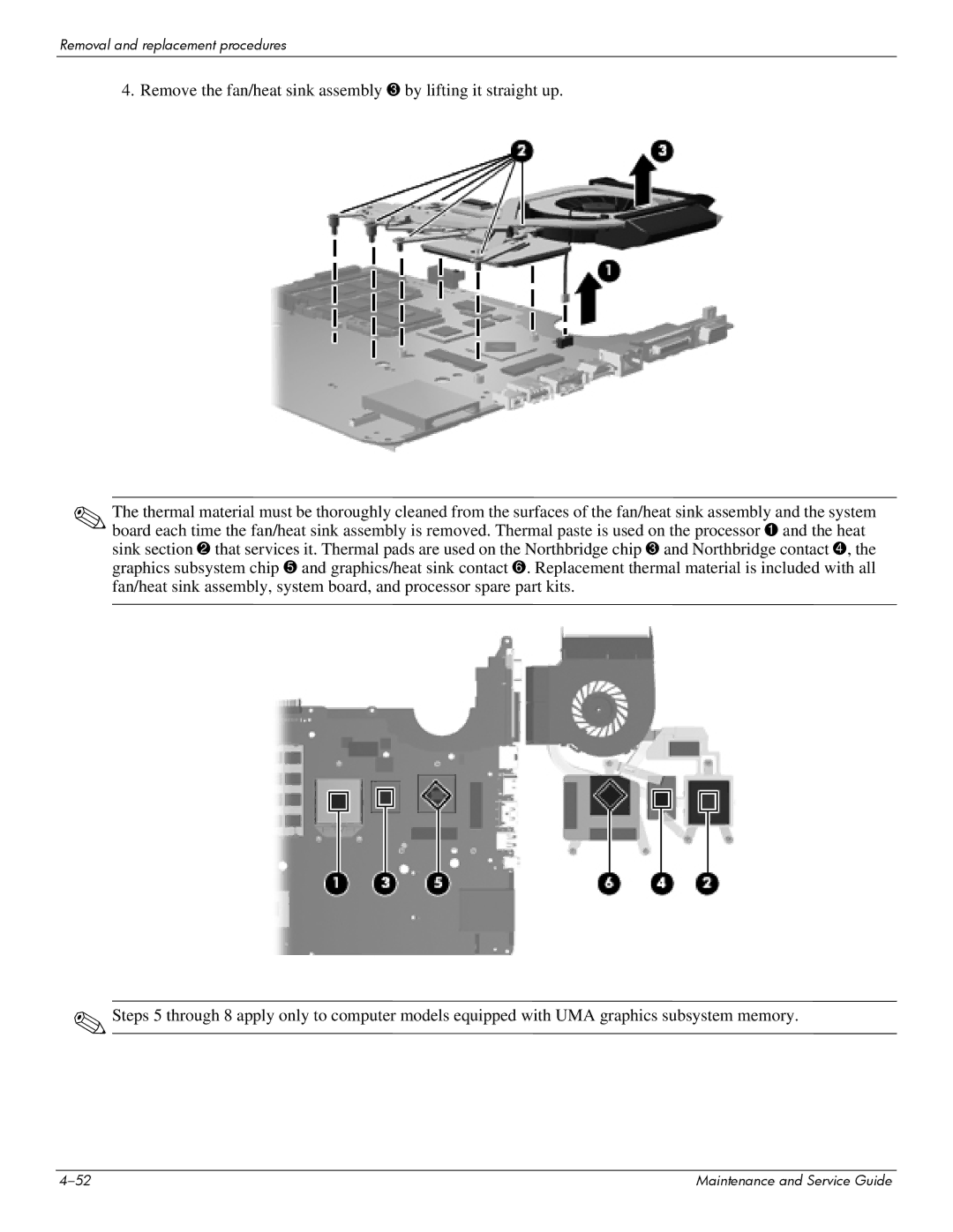
4. Remove the fan/heat sink assembly 3 by lifting it straight up.
✎The thermal material must be thoroughly cleaned from the surfaces of the fan/heat sink assembly and the system board each time the fan/heat sink assembly is removed. Thermal paste is used on the processor 1 and the heat sink section 2 that services it. Thermal pads are used on the Northbridge chip 3 and Northbridge contact 4, the graphics subsystem chip 5 and graphics/heat sink contact 6. Replacement thermal material is included with all fan/heat sink assembly, system board, and processor spare part kits.
✎Steps 5 through 8 apply only to computer models equipped with UMA graphics subsystem memory.
Maintenance and Service Guide |