Maintenance and Service Guide
HP Pavilion dv7 Entertainment PC
Page
Page
Safety warning notice
Contents
Setup Utility
11Recycling
Index
Product description
Chipset
Panels
Hard drives
Webcam
Microphone
Audio
Modem
External media card
Internal card
Expansion
Ports
Power requirements
Operating system Preinstalled
Serviceability End-user replaceable parts
Pointing devices
External component identification
Top components
Display components
Component Description
TouchPad
Component Function
System and Security Power Options
Buttons
Keys
Component Function Esc key
Lights
Front components
Rear component
Left-side components
Component
Component Function
Right-side components
Bottom components
Service tag
Illustrated parts catalog
Computer major components
Switch cover, Moonlight White includes LED board and cable
Item Description Spare Part Number
Display internal components
Keyboard in Espresso Black color with painted finish
Bluetooth module
7a Bluetooth cable
7c Modem module connector cable and RJ-11 jack
Speaker assembly
USB connector
Optical drive board
Subwoofer
DVB-T TV tuner module
RTC battery
Hard drive covers for primary and secondary hard drives
Wlan module Broadcom 4312 802.11b/g Wlan module
Broadcom 4322 802.11a/b/g/n Wlan module
Atheros 9285G 802.11b/g Wlan module
Battery
Atheros 9280AGN 802.11a/b/g/n Wlan module
516324-001
Display assembly components
Flush glass display assembly spare parts
Webcam/microphone module
Bottom hinge cover
BrightView display assembly spare parts
Display panel
Display Screw Kit not illustrated
Description Spare part number Display bezel 516305-001
Cable Kit
Mass storage devices
Miscellaneous parts
Sequential part number listing
Portugal, Spain, and Sweden
White includes wireless antenna transceivers and cables
United States, and the U.S. Virgin Islands
Black with molded finish
Cable Kit on page 3-12for more Cable Kit information
Removal and replacement procedures
Preliminary replacement requirements
Service considerations
Tools required
Grounding guidelines
Drive handling
Packaging and transporting guidelines
Equipment guidelines
Material Use Voltage protection level
Component replacement procedures
Service tag
Computer feet
Battery
Optical drive
Hard drive covers
Primary hard drive cover
Secondary hard drive cover
Removal and replacement procedures
Hard drive
Removal and replacement procedures
Memory module
Wlan module
Atheros 9285G 802.11b/g Wlan Adapter
Maintenance and Service Guide
Removal and replacement procedures
RTC battery
Description Spare part number RTC battery 449729-001
TV tuner module
Switch cover and keyboard
French Canada 516357-121
Removal and replacement procedures
Removal and replacement procedures
Power button board
Speaker assembly
Description Spare part number Speaker assembly 531902-001
Bluetooth module
Description Spare part number Bluetooth module 537921-001
Display assembly
Primary hard drive see Hard drive on
Removal and replacement procedures
Removal and replacement procedures
Removal and replacement procedures
Removal and replacement procedures
Removal and replacement procedures
Removal and replacement procedures
Removal and replacement procedures
Removal and replacement procedures
Top cover
Removal and replacement procedures
Removal and replacement procedures
System board
Subwoofer cable 2 select models only USB board cable
Removal and replacement procedures
Modem module
510100-001
Removal and replacement procedures
Audio/infrared board
USB board
Subwoofer
Description Spare part number Subwoofer 516333-001
TV tuner module cable
Modem module cable
Power connector cable
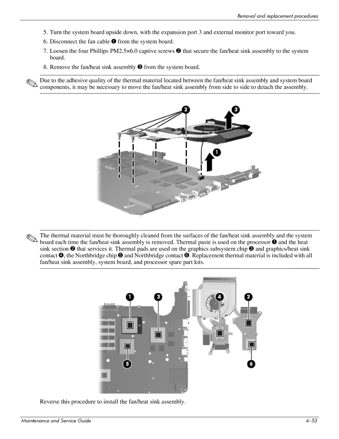
Fan/heat sink assembly
Removal and replacement procedures
Removal and replacement procedures
Processor
Removal and replacement procedures
Setup Utility
Starting the Setup Utility
Using the Setup Utility
Changing the language of the Setup Utility
Navigating and selecting in the Setup Utility
Restoring default settings in the Setup Utility
Displaying system information
Setup Utility menus
Exiting the Setup Utility
Main menu
Security menu
System Configuration menu
Diagnostics menu
Primary Hard Disk Self Test
Specifications
Computer specifications
Input power
Temperature
Metric Dimensions
Pixel resolution
Total power consumption Viewing angle
Metric Maximum altitude unpressurized
Inch HD+ BrightView display specifications
Hard drive specifications
Access time
Transfer mode Multiword DMA Mode
Applicable disc Read Write
Cache buffer Data transfer rate
System DMA specifications, AMD
Direct memory access controller
Hardware DMA System function
System interrupt specifications, AMD discrete graphics
Hardware IRQ System function
System interrupt specifications, AMD UMA graphics
System I/O address specifications, AMD
Address hex System function shipping configuration
Address hex System function shipping configuration
System memory map specifications, AMD discrete graphics
Size Memory address System function
System memory map specifications, AMD UMA graphics
Screw listing
Phillips PM2.5×7.0 screw
Color Quantity Length Thread Head diameter Black
Screw listing
Screw listing
Screw listing
Phillips PM2.5×6.0 captive screw
Color Quantity Length Thread Head diameter Silver
Screw listing
Screw listing
Phillips PM2.0×4.0 screw
Color Quantity Length Thread Head diameter Silver
Phillips PM2.5×4.0 screw
Phillips PM2.5×4.0 screw
Phillips PM3.0×4.0 screw
Phillips PM2.0×3.0 screw
Screw listing
Screw listing
Phillips PM2.5×5.0 screw black
Phillips PM2.5×5.0 screw silver
Phillips PM2.5×5.0 broadhead screw black
Phillips PM2.5×5.0 broadhead screw silver
Phillips PM2.0×2.0 broadhead screw
Backup and recovery
Recovering system information
Creating recovery discs
Backing up your information
Using Windows Backup and Restore
Using system restore points
Performing a recovery
Recovering from the recovery discs
Connector pin assignments
Pin Signal
1394
Audio-in microphone
Audio-out headphone
External monitor
Hdmi
RJ-11 modem
RJ-45 network
Universal Serial Bus
Power cord set requirements
Requirements for all countries or regions
Requirements for specific countries or regions
Country/region Accredited agency Applicable note number
Battery
Recycling
Display
Recycling
Maintenance and Service Guide 11-3
11-4
Maintenance and Service Guide 11-5
11-6
Index
Esc 2-4fn 2-4function 2-4keypad
Maintenance and Service Guide Index-3
Maintenance and Service Guide Index-4
Maintenance and Service Guide Index-5