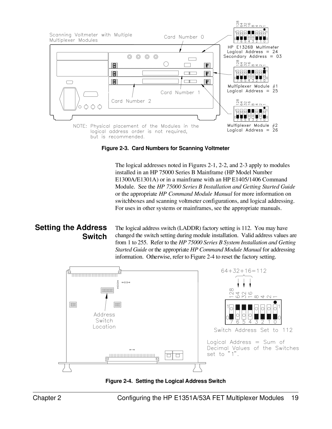
Figure 2-3. Card Numbers for Scanning Voltmeter
Setting the Address Switch
The logical addresses noted in Figures
The logical address switch (LADDR) factory setting is 112. You may have changed the switch setting during module installation. Valid address values are from 1 to 255. Refer to the HP 75000 Series B System Installation and Getting Started Guide or the appropriate HP Command Module Manual for addressing information. Otherwise, refer to Figure
Figure 2-4. Setting the Logical Address Switch
Chapter 2 | Configuring the HP E1351A/53A FET Multiplexer Modules 19 |