Connecting Field Wiring
| Leads for the individual channels are connected through the channel |
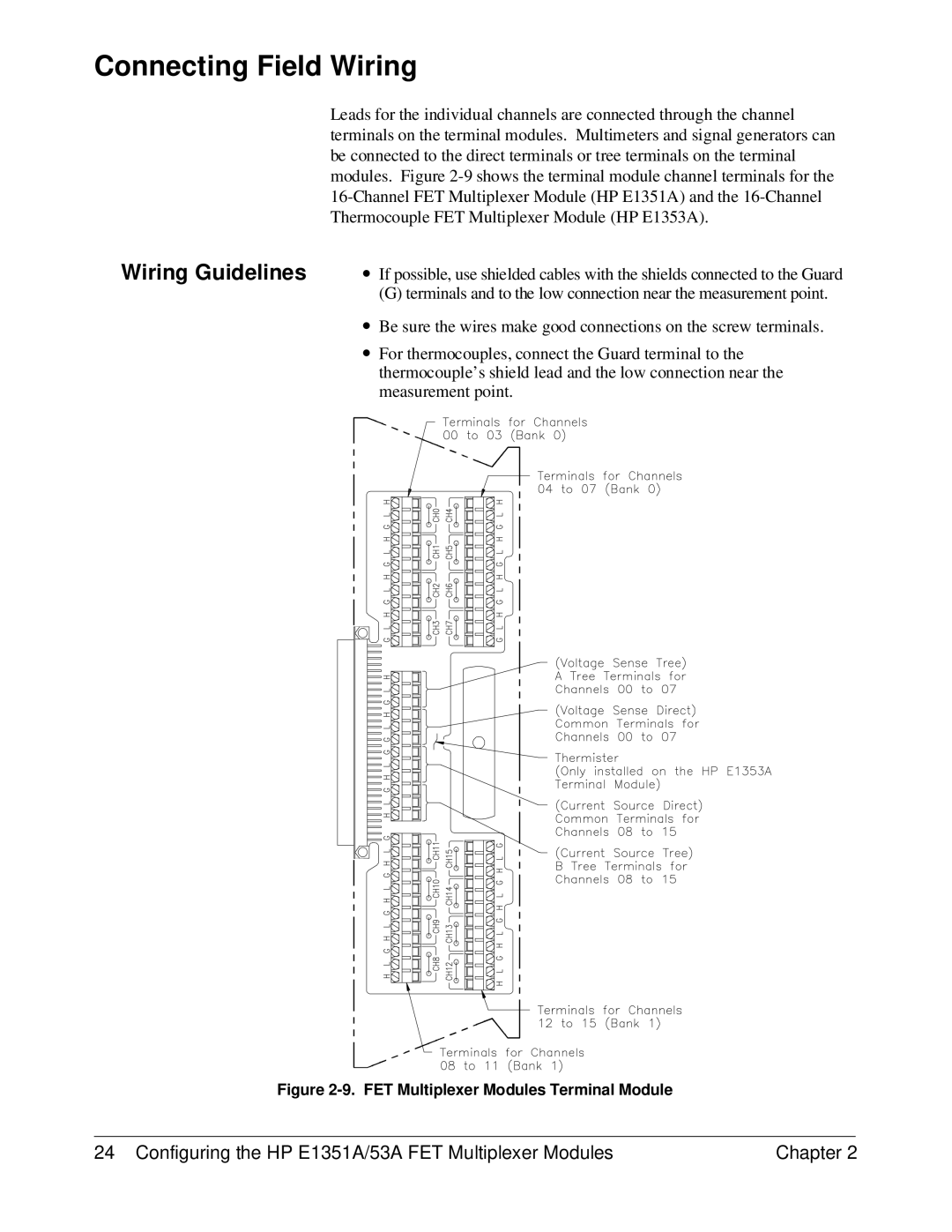
| terminals on the terminal modules. Multimeters and signal generators can |
| be connected to the direct terminals or tree terminals on the terminal |
| modules. Figure |
| |
| Thermocouple FET Multiplexer Module (HP E1353A). |
Wiring Guidelines | ∙ If possible, use shielded cables with the shields connected to the Guard |
| (G) terminals and to the low connection near the measurement point. |
| ∙ Be sure the wires make good connections on the screw terminals. |
| ∙ For thermocouples, connect the Guard terminal to the |
| thermocouple’s shield lead and the low connection near the |
| measurement point. |
Figure 2-9. FET Multiplexer Modules Terminal Module
24 Configuring the HP E1351A/53A FET Multiplexer Modules | Chapter 2 |