Advanced configuration example
This example server has four NUMA nodes with eight
To avoid this situation, you must manually configure the affinity of the IO Accelerator devices using the FIO_AFFINITY configuration parameter to distribute the work load across all NUMA nodes. This parameter overrides the default behavior of the IO Accelerator driver. For more information about the FIO_AFFINITY configuration parameter, refer to the syntax explanation below.
Syntax:
The following is an example of how to configure 10 HP IO Accelerator ioDrive Duo devices (each with two IO Accelerator devices) in a HP DL580 G7 system manually as described in the preceding paragraphs. Slot 1 is a Generation 1 PCIe slot, so it is not compatible with an ioDrive Duo device. Therefore you can fill slots
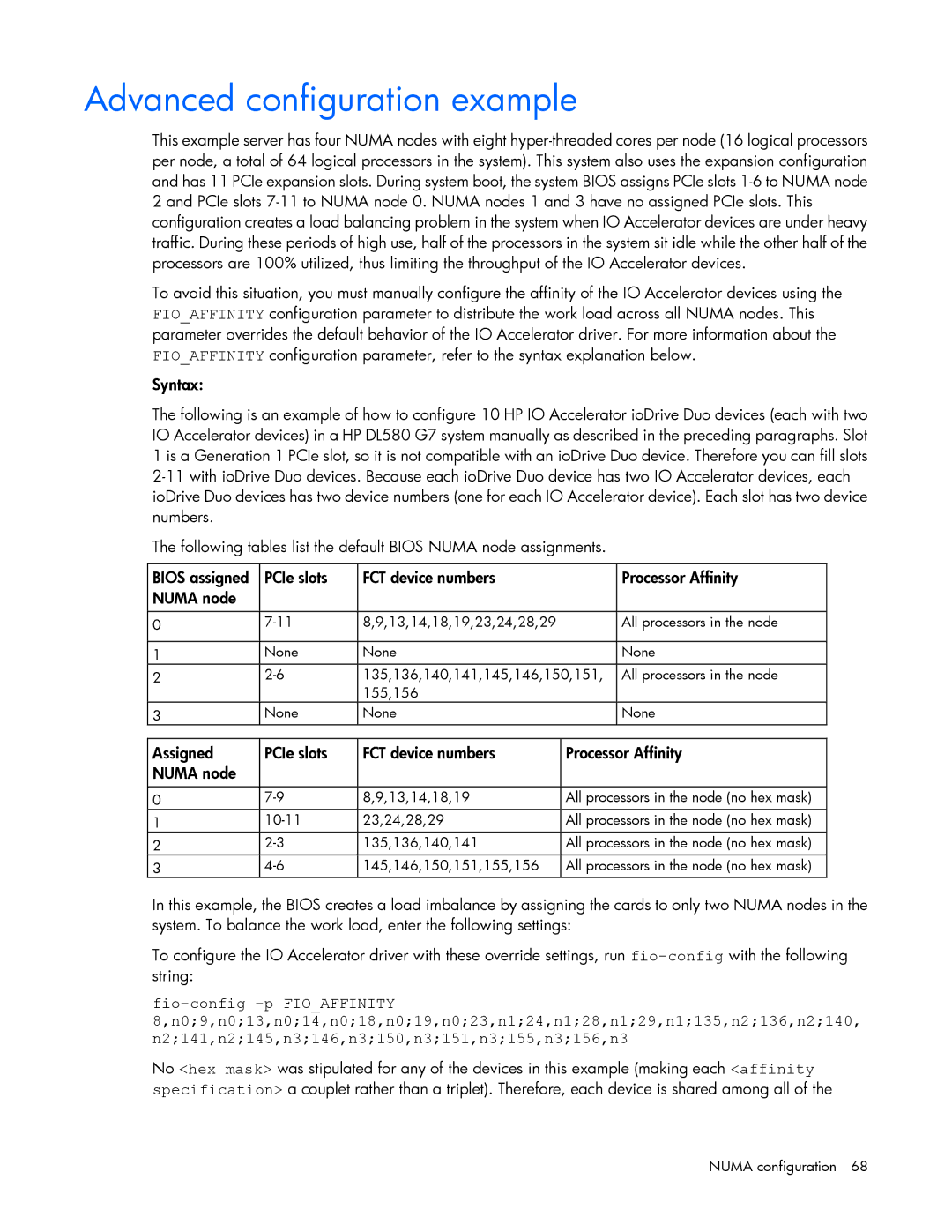
The following tables list the default BIOS NUMA node assignments.
BIOS assigned | PCIe slots | FCT device numbers | Processor Affinity |
NUMA node |
|
|
|
|
|
|
|
0 | 8,9,13,14,18,19,23,24,28,29 | All processors in the node | |
|
|
|
|
1 | None | None | None |
2 | 135,136,140,141,145,146,150,151, | All processors in the node | |
|
| 155,156 |
|
3 | None | None | None |
Assigned | PCIe slots | FCT device numbers | Processor Affinity |
NUMA node |
|
|
|
|
|
|
|
0 | 8,9,13,14,18,19 | All processors in the node (no hex mask) | |
1 | 23,24,28,29 | All processors in the node (no hex mask) | |
2 | 135,136,140,141 | All processors in the node (no hex mask) | |
3 | 145,146,150,151,155,156 | All processors in the node (no hex mask) |
In this example, the BIOS creates a load imbalance by assigning the cards to only two NUMA nodes in the system. To balance the work load, enter the following settings:
To configure the IO Accelerator driver with these override settings, run
No <hex mask> was stipulated for any of the devices in this example (making each <affinity specification> a couplet rather than a triplet). Therefore, each device is shared among all of the
NUMA configuration 68
